This topic describes how to control the RMC over an EtherNet/IP I/O connection. For details on setting up a connection, see the Setting up an EtherNet/IP I/O Connection topic.
Understanding the Sync Register
A cyclic I/O data connection with the RMC can operate in one of two modes: without a Sync Register and with a Sync Register. Delta normally recommends using the Sync Register.
Without a Sync Register:
The RMC processes incoming data each time any register in the block changes.
With
a Sync Register:
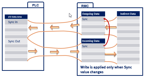
The first Input Data register and first Output Data register are each reserved
as a Sync Register, and the RMC processes incoming data only when the
Sync Register changes. Once the incoming data has been processed, the
incoming Sync Register value is echoed in the outgoing data. For RMCs
that support multiple I/O connections, each connection has a Sync Register.
The Sync Registers show up in the Input and Output Data images in the PLC.
In the RMC, they are only visible in the Event Log. See Troubleshooting
EtherNet/IP I/O for details.
Why Use a Sync Register?
The Sync Register gives the user tight control over synchronization between the PLC and RMC and helps prevent synchronization issues in the communication logic. In applications that do not require this level of synchronization, the user can choose to not include the Sync Register.
The synchronization provided by the Sync Register is useful when:
Treating writes to a block of registers as a consistent block.
Not all PLCs synchronize their I/O with the PLC scan. Therefore, while data is being placed in the Output Data by the PLC program, a copy of the Output Data could prematurely be sent to the RMC, mixing some old data with some new data. When the Sync Register is used, this problem is avoided by the simple convention of having the PLC program update the Sync Register after all other registers have been set to the desired values. The RMC is then guaranteed to receive all the data in a single block.
Coordinating when Input Data has been updated to reflect an issued command.
This benefit is best demonstrated with an example. Suppose that an axis is holding position with its In Position status bit set. If the PLC issues a new move command to a new position, then we will see that the In Position bit will go off when the command is first processed and remain off until the new move completes and the axis is at the new position. How then does the PLC know when its copy of the In Position bit received in the Input Data reflects the new command having been received? When the Sync Register is used, the PLC can simply wait until the Sync Register coming from the RMC matches the one it sent to the RMC when issuing the command, and it can then safely examine the In Position bit.
Setting the Sync Register Mode
To select whether the Sync Register is used:
In the Project pane, expand the Modules folder, double-click the CPU module, and choose the EtherNet/IP page.
In the I/O Connection Settings section, check the Use a Sync Register box to use the sync register, or clear the box to not use it. If the RMC supports multiple I/O Connections, make sure to set the Sync Register setting as desired for each connection. Not using the Sync Register is not supported by RMC75/150 firmware 3.38.0 or older.
Using Input Data in the PLC
If the Sync Register is used for a connection, then the first register of the Input Data is reserved as the Sync Register. All other registers in the Input Data are defined by the Outgoing Cyclic I/O Data address specified in the EtherNet/IP Settings Page. When the I/O connection is established, the Input Data is automatically updated in the PLC at the Requested Packet Interval (RPI). The PLC can simply use the data whenever it needs it. The RMC does not wait for the Sync Register to change to update its Outgoing Cyclic I/O Data.
Care must be taken to consider the data types of each Input Data register. The RMC includes registers of type REAL, DINT, and DWORD, and when you assign the Outgoing Cyclic I/O Data, you have the ability to mix registers of different types in the Input Data. It may be necessary to copy the data from one type of memory to another in the PLC to ensure that it gets interpreted correctly. For example, on Allen-Bradley PLCs, the COP and CPS instructions can be used to copy the data from an array of one type to tags of the correct type.
Writing Output Data with a Sync Register from the PLC
To write data in the RMC controller using I/O data when the Sync Register is used, do the following in the PLC:
Wait for the Sync Registers in the Input Data and Output Data to match.
Update any Output Data register values, except the Sync Register.
Change the value of the Output Data Sync Register.
The easiest way to do this is to add one to it. However, since the Sync register is a 32-bit floating point value, one cannot be added to it after it reaches 16,777,216. One method of handling this is to add one and then MOD it with some large number, such as 1,000. This will make the register count from 0 to 999, and then wrap back down to 0 without an error. Take care to ensure that you only update the Sync Out register once so that the commands do not get re-issued.
Do not change any Output Data registers until the Input and Output Sync Registers match again.
The RMC will apply the Output Data register contents only once.
For multiple connections to one RMC, each connection has an individual Sync Register. The connections are independent of each other, and the data may not be transferred at exactly the same time, even if the Sync Registers are changed simultaneously. Therefore, it is best practice that for data that must be sent simultaneously, that they are sent in the same Output Data block.
Writing Output Data without a Sync Register from the PLC
To write data in the RMC controller using I/O data without the Sync Register, simply change the Output Data registers in the PLC and they will get applied in the RMC. Often care must be taken as to the order that the registers are updated to ensure that actions triggered by changes to registers in the RMC have updated values for any parameters they use. It is often necessary to also understand whether the I/O data is updated synchronously to the PLC scan or not. For multiple connections to one RMC, the connections are independent of each other, and the data may not be transferred at exactly the same time.
Writing to the Command Area from the PLC
The Incoming Cyclic I/O Data area can be set up to point to the Command Area registers directly, or indirectly through the Indirect Data Map. The Sync Register should always be used if the PLC will be writing commands to the Command Area. The following sequence is recommended:
Wait Until the Sync In and Sync Out Registers Match
If they do not match, then this means that another command or set of commands is in progress.
Clear Old Commands from the Command Registers
Clear old commands from the command registers for each axis. Otherwise, when the Sync Out register is changed, the commands would be re-issued. One method of clearing the old commands is to fill the Output Data array with zeroes.
Write to the Command Registers
Write the Command registers and all required command parameters to the Output Data for all commands you want to issue. You can issue up to one command per axis. Leave the Command register set to 0 for each axis that will not receive a command.
Change the Sync Out Register
The easiest way to do this is to add one to it. However, since the Sync register is a 32-bit floating point value, one cannot be added to it after it reaches 16,777,216. One method of handling this is to add one and then MOD it with some large number, such as 1,000. This will make the register count from 0 to 999, and then wrap back down to 0 without an error. Take care to ensure that you only update the Sync Out register once so that the commands do not get re-issued.
Wait Until the Sync In and Sync Out Registers Match
It is important to wait until this occurs before using the status bits in the Input Data (if the Input Data includes any status bits).
For multiple connections to one RMC, each connection has an individual Sync Register. The connections are independent of each other, and the data may not be transferred at exactly the same time, even if the Sync Registers are changed simultaneously. Therefore, it is best practice that if commands need to be sent simultaneously, that they are sent in the same Output Data block.
Triggering Commands through the Variable Table
If you have set the Output Data to write to Variable Table registers directly or via the Indirect Data Map, you can use them together with the Program Triggers to start User Programs that issue commands. For advanced applications that require issuing commands and writing to variables, this can be a very efficient method of communication.
To issue a command with this method, you will first need to do the following:
Create a user program that contains the commands you need.
Define a variable in the Variable Table that will be used to start the program. Name it StartProgram, for example.
Create a Program Trigger condition that looks at the value of StartProgram. When the StartProgram variable becomes a certain value, it will start the specified user program. This StartProgram variable can be used to start different programs based on its value.
The user programs should always reset the StartProgram variable to some starting value (such as 0). This is so the Program Triggers will always see the number change when the PLC writes to it. If the number already was 6, and the PLC writes 6, the value doesn't change, and the Program Triggers do not know to start a user program. Typically, the first step in a program should reset the value of the variable.
Once you have created the Program Triggers and User Programs, make sure the RMC is in RUN Mode, and use one of the procedures below to start a User Program:
With a Sync Register:
Wait until the Sync In and Sync Out Registers match.
Write a number to the StartProgram variable. The number will specify which user program to run.
If you need to write to other variables (e.g. for defining speeds, setpoints, etc.), do so.
Change the Sync Out Register.
The easiest way to do this is to add one to it. However, since the Sync register is a 32-bit floating point value, one cannot be added to it after it reaches 16,777,216. One method of handling this is to add one and then MOD it with some number, such as 1,000. This will make the register count from 0 to 999, and then wrap back down to 0 without an error. Take care to ensure that you only update the Sync Out Register once so that the commands do not get re-issued.
Wait until the Sync In and Sync Out Registers match.
When the Sync In Register has changed, you know the data has been applied to the RMC. It is important to wait until this occurs before using the status bits in the Input Data (if the Input Data includes any status bits).
After the Sync registers match, you can look at the Task Status and Current Program registers to determine if the task is running the program, and when it stops. These registers should be included in the Input Data.
Without a Sync Register
If you need to write to other variables that are used by the user program (e.g. for defining speeds, setpoints, etc.), do so first.
Write a number to the StartProgram variable. The number will specify which user program to run.
Handling Broken Connections
Many applications require some type of action if the EtherNet/IP I/O connection breaks during machine operation. For information on how to handle a broken connection in either the RMC or PLC, see the Handling Broken EtherNet/IP Connections topic.
Troubleshooting
See the Troubleshooting EtherNet/IP I/O topic.
How the I/O Data is Applied to the RMC
When the Sync
register is used:
When the RMC sees that the Sync Register changes for a given connection,
the RMC applies all the data from the PLC to the specified Incoming Cyclic
I/O Data area, for that connection.
When
the Sync Register is not used:
When the RMC sees that any register value changes for a given connection,
the data for that connection is immediately written to the specified Incoming
Cyclic I/O Data area.
In certain cases, it may take the RMC more than one loop time to apply the incoming data. Therefore, not all of the data may be valid at the same time. For example, if you are using any of the data to trigger a user program that also uses some of the data, it is important that the user program is not triggered before all the data is valid, otherwise, the user program may use old data. The RMC takes at least one loop time per connection to apply the data.
Data Consistency
When all the incoming data is applied in the same RMC loop time, the data is called consistent. If the data is consistent, you can use all the data immediately. If the data is not consistent, you need to make sure that you do not use the data until it has all been updated. For multiple connections to one RMC, the data between connections should be assumed to not be consistent.
The following rules apply to data consistency within a single given connection based on where the consuming address is in the RMC:
Variable Table - Current Values
1 ms or longer loop time: Up to 256 variables can be written at once within a single motion loop. If more than 256 variables are being written to by the I/O connection, then the first 256 variables will be written on the first motion loop, and the remaining variables will be written on the next motion loop.
500 us loop time: Up to 128 variables can be written at once within a single motion loop. If more than 128 variables are being written to by the I/O connection, then 128 variables will be written each motion loop until the entire transaction is done.
250 us or shorter loop time: Up to 64 variables can be written at once within a single motion loop. If more than 64 variables are being written to by the I/O connection, then 64 variables will be written each motion loop until the entire transaction is done.
Command Area
Writing the data to the Command Area may take up to 3 ms. After the write is complete, the entire command block is submitted as a single consistent block. Therefore the data is treated as a single consistent block, although it may take several loop times before the block is submitted.
Indirect Data Map
The only data guaranteed to be consistent are variables, if they are placed first in the Incoming Data area of the Indirect Data Map. The size of guaranteed consistent data depends on the loop time:
1 ms or longer loop time: The first 100 registers will be consistent if they are all variables.
500 us loop time: The first 50 registers will be consistent if they are all variables.
250 us or shorter loop time: The first 25 registers will be consistent if they are all variables.
As soon as the first register is encountered that is not a current or initial variable register, the guarantee for data consistency no longer applies. Remaining registers in the I/O block will be processed as time allows on subsequent motion loops, taking up to a maximum of 10 ms. For this reason, variables should be included first in the Incoming I/O Data Area of the Indirect Data Map in order to ensure their consistency.
Notice that if commands are mapped to the Indirect Data, the commands will all be submitted at the same time, after all values have been written.
Other Locations
No data consistency is guaranteed when consuming in other areas (such as axis parameters). The entire write can take as long as 10 ms, with the write being deferred to the next control loop at any point as required to meet loop time requirements.
See Also
EtherNet/IP Overview | Setting up an EtherNet/IP I/O Connection | Handling Broken EtherNet/IP I/O Connections | Troubleshooting EtherNet/IP I/O | Multiple EtherNet/IP I/O Connections | EtherNet/IP I/O Performance | Using Allen-Bradley Controllers via EtherNet/IP I/O | Using Omron Controllers via EtherNet/IP I/O
Copyright © 2026 Delta Computer Systems, Inc. dba Delta Motion