Handling Broken EtherNet/IP I/O Connections
It is important to detect loss of an EtherNet/IP
I/O connection quickly. EtherNet/IP supports a variable timeout value,
which is expressed in terms of Requested Packet Intervals (RPIs). The
RMC supports multipliers ranging from 4x to 512x. The PLC may allow you
to select this timeout multiplier value, or may fix it to a certain value.
For example, the ControlLogix establishes its EtherNet/IP I/O connections
with a timeout of 32 RPIs. Therefore, an RPI of 4.0 ms will have a timeout
of 32 x 4.0 ms or 128 ms.
When either device in an I/O connection does
not receive a packet from the other device for the timeout interval, it
closes the connection and typically indicates this condition to the main
program. The method of indicating this condition depends on the actual
device. This topic describes the methods used by the RMC and several common
PLCs.
Handling Broken I/O Connections in the RMC
The RMC has tags that indicate the state of
the I/O connections. The user can use these tags to qualify whether certain
operations in the User Programs can be done, or they can use these tags
in the Program Triggers to respond to the change in state of the connection.
To find these tags when editing the Program
Triggers or a User Program, use the Address Selection tree and browse
to:
Controller
> Communication Settings > Ethernet
Handling Broken I/O Connections in the PLC
The method of detecting and handling a broken
EtherNet/IP I/O connection varies from PLC to PLC. Review the documentation
included with your PLC or EtherNet/IP communication card for details.
Some PLC detection procedures are shown below. However, these are not
comprehensive procedures and do not cover all PLCs.
 Allen-Bradley ControlLogix and CompactLogix
PLCs
Allen-Bradley ControlLogix and CompactLogix
PLCs
The ControlLogix and CompactLogix controllers have two methods of handling a broken connection with an EtherNet/IP device such as the RMC:
-
Major Fault if Connection Fails:
In RSLogix 5000, in the Module Properties dialog box for the RMC, on the Connection tab, the Major Fault On Controller If Connection Fails In Run Mode check box can be checked to fault the ControlLogix when the EtherNet/IP connection to the RMC is broken.
-
Connection Status Tags:
For EDS File:
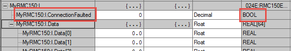
If an EDS file was used to configure the connection, the input tag for each connection has a ConnectionFaulted boolean tag that can be used to read the status of the connection in ladder logic:
For Generic Ethernet Module:
If the connection was configured as a Generic Ethernet Module, the Get System Value (GSV) block must be used to read the status of the connection in ladder logic. The following ladder logic demonstrates this:
The core of this ladder segment is reading the EntryStatus and FaultCode attributes from the RMC MODULE object using the GSV blocks. The MODULE objects are internal to the ControlLogix and represent external modules. In the Instance Name field of the GSV blocks, type the name you selected for the particular RMC module.
If the connection to the module is running, then the high four bits of the EntryStatus will be equal to 4 and the FaultCode will be equal to 0. This is described in the RSLogix 5000 online help's "Accessing the MODULE Object" topic.
The above ladder masks off the low 12 bits of the EntryStatus using an AND block, and then sets the RMCConnFault coil to indicate whether or not the connection is faulted.
Omron CS1/CJ1/CJ2 PLCs
Refer to section 6-3-1 Ladder Programming Related to Tag Data Links in the SYSMAC CS and CJ Series EtherNet/IP Units Operation Manual (document W-465-E1-06) from Omron. This section describes using four flags to determine that the I/O communications are operating normally with a specific target:
-
The Unit Error Occurred Flag (n+10, bit 00) must be OFF.
-
The Online Flag (n+11, bit 00) must be ON.
-
The Tag Data Link Operating Flag (n+11, bit 01) must be ON.
-
The Normal Target Node Flag (in words n+20 to n+23) for the corresponding target node must be ON.
Notice that the Target Node PLC Operating Flag and Target Node PLC Error Flag also discussed in this section are not used with RMC controllers.
Please refer to the above-referenced section of the Omron manual for additional information including differences between Omron EtherNet/IP Unit revisions and example ladder logic.
Schneider Electric Quantum, Premium,
and Modicon M340 PLCs
Detecting a broken EtherNet/IP I/O connection on the Schneider Quantum and Premium PLCs involves testing the appropriate connection health status bit in the EtherNet/IP controller’s Derived Data Type (DDT) Variables.
The procedure for determining the location of the appropriate bit differs between the first and second generation of communication modules from Schneider Electric:
Quantum 140 NOC 771 00 and Premium TSX ETC 100 Modules:
These status bits are located in the DDT input structure in a field called Status, which is an array of 16 BYTEs. To determine the correct bit to check for a given target device, you must locate the Connection Bit Health Offset field for the device:
-
Open the Unity Pro EtherNet/IP Configuration Tool.
-
Open the properties for the desired target device.
-
Select the Connection tab.
-
Under Configured Connections, select the General item for the connection whose status you want to monitor. In most cases, there will only be a single connection in this list.
-
Under Connections Parameters, locate the item named Connection Bit Health Offset. This is usually the first item in the list. This should be a value in the range of 0..127.
The value of the Connection Bit Health Offset is the bit offset from the start of the 16-byte Status[] array located in the Derived Variables for the EtherNet/IP controller (140 NOC 711 00 or TSX ETC 100). Offsets 0-7 correspond to Status[0].0 to Status[0].7, offsets 8-15 correspond to Status[1].0 to Status[1].7, and so on. If this bit is 1, then the connection is healthy. If this bit is 0, then the connection has been lost.
Quantum 140 NOC 771 01, Premium TSX ETC 101, and Modicon M340 BMX NOC 0401 Modules:
These status bits are located in the DDT input structure in a field called Status, which is an array of 16 BYTEs. To determine the correct bit to check for a given target device, you must locate the Connection Bit field for the device:
-
Start Unity Pro.
-
In the DTM Browser, right click on the Ethernet communication module (named ‘NOC01’ in this example) and click Open.
-
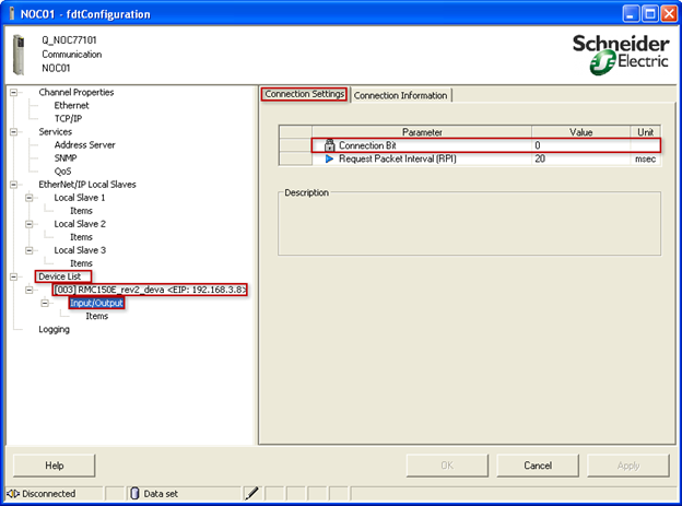
In the NOC01 – fdtConfiguration window, in the left-side tree, expand the Device List group, expand the target device (RMC) that you want to look at, and select the connection node named Input/Output, which will generally be the only connection listed. Then in the right part of the window, select the Connection Settings tab, and look at the Connection Bit value, which should be in the range of 0..127:
The value of the Connection Bit is the bit offset from the start of the 16-byte HEALTH_BITS_IN [] array located in the input Derived Variable created for the EtherNet/IP communication module. For example, for a module named NOC01, offsets 0-7 correspond to NOC01_IN.HEALTH_BITS_IN[0].0 to NOC01_IN.HEALTH_BITS_IN[0].7, offsets 8-15 correspond to NOC01_IN.HEALTH_BITS_IN[1].0 to NOC01_IN.HEALTH_BITS_IN[1].7, and so on. If this bit is 1, then the connection is healthy. If this bit is 0, then the connection has been lost.
See Also
EtherNet/IP
Overview | I/O
Connection Status | I/O
Connection PLC State
Send comments on this topic.
Copyright © 2025 Delta Computer Systems, Inc. dba Delta Motion