Several Schneider Electric PLCs support EtherNet/IP I/O communication via plug-in Ethernet communication modules. This topic describes how to use Quantum 140 NOC 771 01, Premium TSX ETC 101, and Modicon M340 BMX NOC 0401 Ethernet communication modules to communicate with the RMC via EtherNet/IP I/O.
Determine I/O Data Locations in the RMC
EtherNet/IP I/O transfers data back and forth between the RMC and PLC at the Requested Packet Interval (RPI). The user must specify which data items in the RMC should be sent and received. Typically, this is data in the Indirect Data Map.
Set up the Indirect Data map so that one part contains all the data coming from the PLC (Incoming Data), and another part contains all the data going to the PLC (Outgoing Data). Make sure the Incoming and Outgoing Data areas in the Indirect Data Map do not overlap.
The Outgoing Data typically includes RMC status items that the PLC always needs to keep track of, such as actual positions and status bits.
The Incoming Data consists of items that the PLC needs to write to in the RMC. This is typically variables and possibly command registers.
Note:
The Incoming and Outgoing Data locations need not be the Indirect Data
Map. However, the Indirect Data Map is usually the best choice. Other
options are the Variable Table and the command area.
Setting Up the RMC for EtherNet/IP I/O
Do the following in the RMC:
Set the RMC's IP Address
Set up the RMC's IP Address as for any Ethernet connection. See Setting Up the RMC Ethernet for details.
Set Up the Indirect Data Map
In the Project pane, double-click Address Maps, then click Indirect Data Map.
Beginning at item 0 in the Indirect Data Map, choose the items for the Outgoing Cyclic I/O Data.
At some location in the Indirect Data Map after the Outgoing Cyclic I/O Data area, choose the items for the Incoming Cyclic I/O Data, that is, the items that will be sent to the RMC from the PLC. If you are using another location for your Incoming Data, such as the Variable Table or Command Area, you need not set up the Indirect Data Map for the Incoming Data.
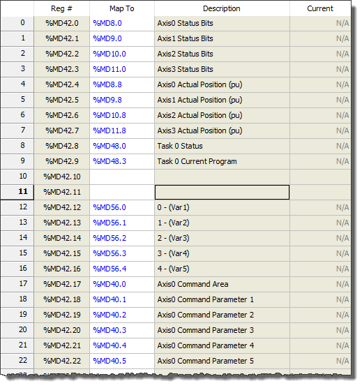
Example
If you have a 4-axis
controller, you may wish to set up the Outgoing Data at the beginning
of the Indirect Data Map to include the Actual Position and the Status
Bits for each axis, in addition to information on Task 0, which perhaps
runs your user programs.
You may also wish to set the Incoming Data, starting at item 12 in the
Indirect Data Map, to go to 5 variables and some of the Axis 0 command
registers. You could then set up the Indirect Data Map like this:
Set the Cyclic I/O Data Locations in the RMC
In the Project pane, expand the Modules folder, double-click the CPU module, and choose EtherNet/IP.
Under Outgoing Data, enter the starting location for the outgoing cyclic I/O data. In our example, verify that the location is the Indirect Data Map Entry 0 Value.
Under Incoming Data, enter the starting address for the incoming cyclic I/O data. This should be a location in the Indirect Data Map, the Variable Table, or Command Area as discussed in the Determine I/O Data Locations in the RMC section above.
Notice that the RMC200 supports up to three I/O connections. However, for Schneider Electric PLCs, it is recommended that only the first I/O connection is used, which supports up to 360 registers in each direction. The settings for I/O Connection 2 and I/O Connection 3 will be ignored.
For example, the EtherNet/IP Settings Page below shows an RMC150 with the Outgoing Data coming from the Indirect Data map starting at item 0 and the Incoming Data going to the Indirect Data starting at item 12.
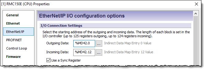
Choose Whether to Use a Sync Register
The Sync Register provides a method for the PLC to synchronize the Input Data and Output Data. If you will be writing to the Command Area directly or indirectly via the Indirect Data Map, Delta recommends using the Sync Register.
With a Sync Register, the Incoming Data is not written to the RMC until the Sync Register change. If you prefer to have the Incoming Data be written whenever any value in the Incoming Data changes, choose the option to not use a Sync Register.
For more details, see Using an EtherNet/IP I/O Connection.
Configuring the Unity PLC Connection
The following procedures describe setting up the EtherNet/IP I/O connection between a Schneider Electric PLC with an RMC using Unity Pro software. The corresponding Schneider Electric documentation for these procedures is the following:
Quantum 140 NOC 771 01 Ethernet Communication Module User Manual (S1A33985.xx)
Premium TSX ETC 101 Ethernet Communication Module User Manual (S1A34003.xx)
Modicon M340 BMX NOC 0401 Ethernet Communication Module User Manual (S1A34009.xx)
These procedures were built using Unity Pro XL V13. They describe using the Quantum 140 NOC 771 01 Ethernet module. The procedures for other versions of Unity Pro and other EtherNet/IP-capable Schneider Electric Ethernet modules are expected to be similar.
Start Unity Pro and ensure the following:
Ensure that the configuration includes the Schneider Electric Ethernet Communication Module. In this example, this module is a 140 NOC 771 01 with the Alias Name of “NOC01”.
Ensure that the IP settings in the Ethernet module are configured and compatible with your network.
Ensure that you are able to go on- and offline with the PLC and to connect and disconnect with the Ethernet module in the DTM Browser.
Ensure that Unity Pro is not in Simulation Mode.
In the main Unity Pro window, ensure that the PLC is disconnected. If you are connected, on the PLC menu, click Disconnect.
Reserve a memory area for the Ethernet module that includes room for all the slave devices you will attach to the module.
In the Project Browser, expand the Configuration node and double-click on the Ethernet communication module, which is a 140 NOC 771 01 in this example: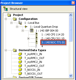
In the property window that opens, select the Configuration tab, and review the Inputs and Outputs sections:
These sections define two blocks of %MW registers, one for inputs into the PLC and one for outputs from the PLC. Refer to the manual for your particular Ethernet module to check how much data is required for the module itself, and then add the data that will be required by the slave devices.
In our example, we will need 11 incoming registers (produced by the RMC) and 12 outgoing registers (consumed by the RMC). Because the RMC uses 32-bit registers and the %MW registers are 16-bit, we need to double each. The revision of the 140 NOC 711 01 Ethernet module used in this example requires 16 %MW registers each for inputs and outputs in addition to the data transmitted with slave devices. Therefore the minimum number of inputs are 38 (11x2 + 16) and the minimum number of outputs are 40 (12x2 + 16)
In this example, we set both sizes to 100 to allow room for adding future devices.
To save these new address and size settings, on the Edit menu, click Validate.
Add the RMC EDS files to the library and hardware catalog. Notice that this procedure is only required once per Unity Pro installation.
If the DTM Browser is not already open, then on the Tools menu, click DTM Browser.
In the DTM Browser window, ensure that the Ethernet communication module is disconnected. If it is connected, then right-click the Ethernet module, and click Disconnect.
In the DTM Browser window, right-click the Ethernet communication module, point to Device menu, point to Additional functions, and then click Add EDS to library.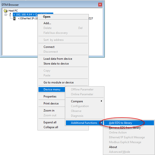
Complete the EDS Addition wizard that follows. When prompted for the location of the EDS files, select the contents of the EDS folder under the RMCTools program folder as shown below: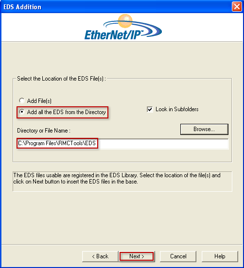
The wizard should confirm that the RMC EDS files will be added, similar to that shown below: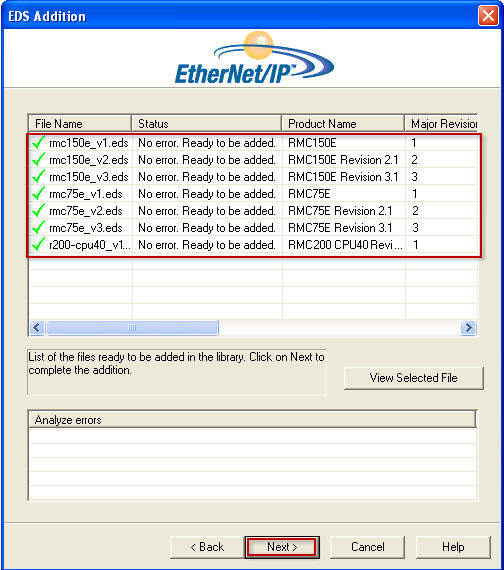
Complete the wizard using the Next and Finish buttons. At this point, the EDS files have been added to the EDS database, but are not yet added to the Hardware Catalog.
Open the Hardware Catalog if it is not already open. To do this, on the Tools menu, click Hardware Catalog.
In the Hardware Catalog window, on the DTM catalog tab, click External Update Tool: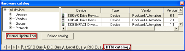
In the FDT/DTM Catalog window, click the Update button.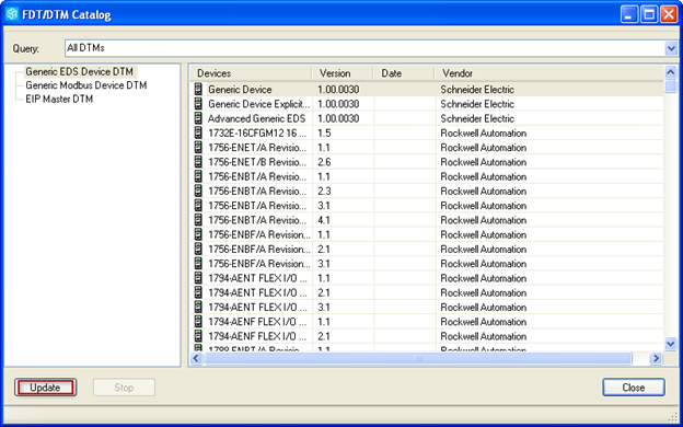
Once the update completes, the RMC devices will be in the Generic EDS Device DTM list. Click Close.
In the Hardware Catalog, on the DTM catalog tab, click Reload catalog: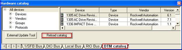
At this point, the RMC controllers are in the Hardware Catalog and can be added as devices to the controller.
Add the RMC to the EtherNet/IP network. There are two methods that can be used to add a device:
OPTION 1: Add the RMC manually.
In the DTM browser, right-click the NOC01 module, and click Add.
In the Add dialog box, find the rows for the RMC product and choose the highest Version number for your RMC (e.g. 3.1 for the RMC150). If you have older firmware, see Setting up an EtherNet/IP I/O Connection for which version to choose.
Click
Add DTM.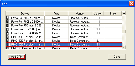
In the Properties
of device window that follows, review and optionally
edit the Alias name
and then click OK: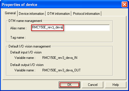
OPTION 2: Add the RMC using Field Bus Discovery.
In the DTM browser, right-click the Ethernet communication module, and then click Connect.
In the DTM browser, right-click the Ethernet communication module, and then click Field bus discovery.
In the Field bus discovery window, select the EtherNet IP channel and CIP (EtherNet/IP) protocol and click OK: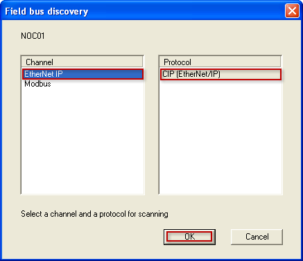
After the discovery completes, you should see a list of RMC controllers found on the network. Select the RMC that you want to add to the network from the Scanned Devices list, select the best matched version in the Matched DTMs list, and then click the green ‘+’ icon to add it: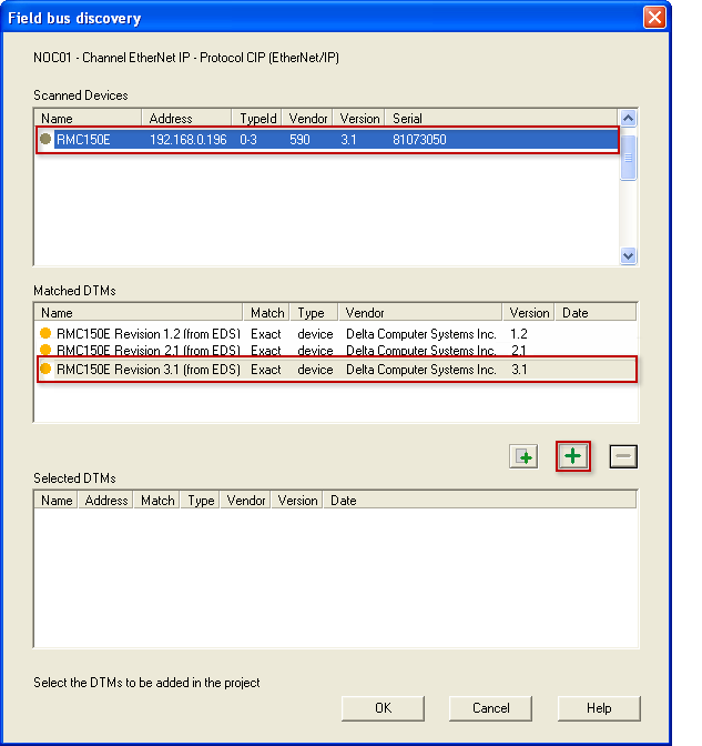
Click OK in the Field bus discovery window when done: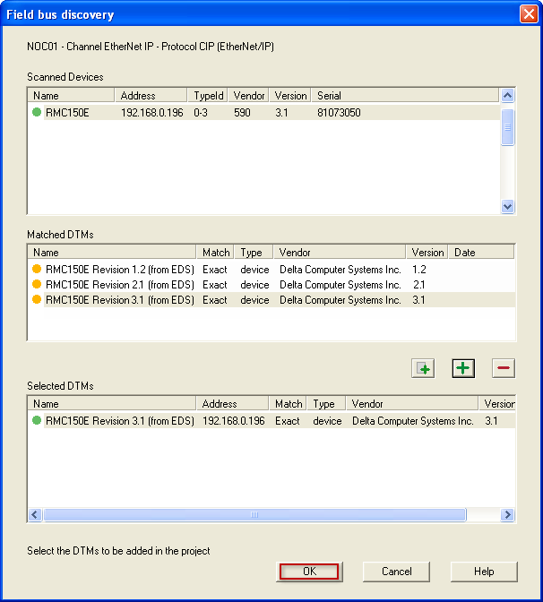
Set the IP address for the RMC.
Notice that if the Field Bus Discovery method was used, then the IP addresses for each RMC are likely already set correctly. Otherwise, the default IP addresses created by the steps above may need to be changed:
In the DTM Browser, if the Ethernet communication module is currently connected, then right-click on the Ethernet module (NOC01) and click Disconnect.
In the DTM Browser, right-click on the Ethernet module (NOC01) device, and click Open.
In the NOC01 - fdtConfiguration window, under Device List, select the RMC device, select the Address Setting tab, and edit the IP Address if necessary. Click OK when done with all changes.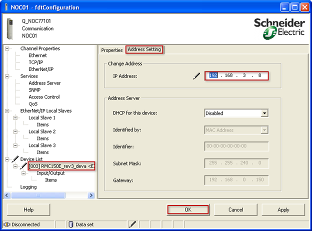
Edit the device configuration for the RMC.
It is necessary to configure the connection data length and update rate.
In the DTM Browser, right-click the RMC device under the Ethernet communication module (NOC01), and click Open.
In the tree on the left, select the Input/Output connection, and select the General tab in the right window pane, and consider the RPI, Input size, Input mode, and Output size parameters, described below: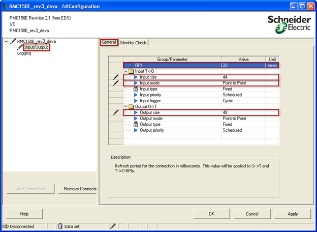
Most of the settings on this page are not editable. However, the following parameters can be changed:
RPI: Select the desired update rate. A commonly-used RPI is 20.0 ms. Very low RPIs may flood the network and reduce network reliability.
Input size: This is the size of the data being produced by the RMC. In this example, we’ll send 10 registers from the Indirect Data Map, plus one Sync register. Each RMC register is 32 bits, or 4 bytes, for a total of 44 bytes.
Input mode: Most EtherNet/IP applications do not share the data produced by the RMC and, therefore, the Input mode should be set to Point to Point to reduce network traffic, but this can be set to Multicast if required.
Output size: This is the size of the data being consumed by the RMC. In this example, we’ll consume 11 registers by the Indirect Data Map, plus one Sync register. Each RMC register is 32 bits, or 4 bytes, for a total of 48 bytes.
Click OK when done.
On the Build menu, click Build Changes.
Add additional RMC devices to your EtherNet/IP network.
Repeat steps 5-7 above for each additional RMC device.
Download the configuration to the PLC.
On the PLC menu, click Connect.
On the PLC menu, click Transfer Project to PLC.
The above steps will register EtherNet/IP I/O
connections for each RMC with the Schneider Electric Ethernet communication
module and create derived variables in the Schneider Electric PLC representing
the data for each RMC. The following screen shot shows the derived variables
created for the example device in the steps above: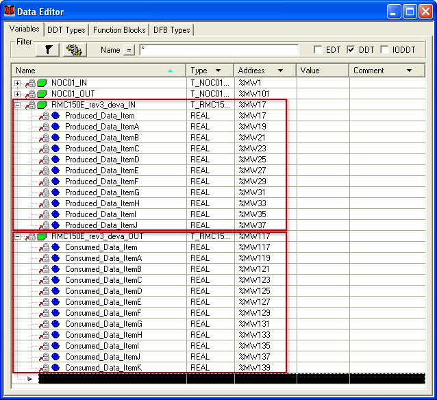
The RMC150E_rev3_deva_IN structure represents data produced by the RMC, starting with the Sync Register followed by the Outgoing Cyclic I/O Data in the RMC, which in this example is %MD42.0-9 from the Indirect Data Map. The RMC150E_rev3_deva_OUT structure represents data consumed by the RMC, starting with the Sync Register followed by the Incoming Cyclic I/O Data in the RMC, which in this example is %MD42.12-22 in the Indirect Data Map.
Performing Communications
Once the EtherNet/IP connection is configured and applied to the PLC, the communications will automatically start, assuming the PLC and RMC are both on a properly set up Ethernet network. Notice that the Omron will communicate even when it is in Program mode.
Reading Data from the RMC
This data will automatically update each Requested packet interval, and you can use the data as you wish. You cannot write to the Input Data. The Input Data will contain the Indirect Data from the RMC. However, if you selected to use the Sync Register, the first item in the Input Data array will be the SyncIn value, followed by the Indirect Data from the RMC.
The SyncIn is used only for synchronizing commands with the logic, as explained below. The SyncIn and SyncOut registers are only visible in the PLC. They are not visible in RMCTools.
Writing to the RMC - General
If you selected to not use a Sync Register, the Output Data is written to the RMC when any value in the Output Data changes.
If you selected to use a Sync Register, the Output Data is sent to the RMC at each Requested Packet Interval, but the RMC ignores it until the SyncOut register changes. The first item in the Output Data array is the SyncOut register, followed by the registers that will be sent to the Incoming Data location in the RMC. Use the following procedure to write to the RMC with a Sync Register:
Wait Until the Sync In and Sync Out Registers Match
If they do not match, then this means that another write is in progress.
Write to the Output Data
Write the desired to the Output Data array.
Change the Sync Out Register
The easiest way to do this is to add one to it. However, you must take care to handle overflowing this register (the Sync register is a REAL). One method is to add one and then MOD it with some large number, such as 10000. This will make the register count from 0 to 9,999, and then wrap back down to 0 without an error.
Wait Until the Sync In and Sync Out Registers Match
This indicates that the RMC has received the data and processed it.
See Using an EtherNet/IP I/O Connection for further details.
Sending Commands to the RMC
If you are writing to the Command Area, either directly or via the Indirect Data Map, Delta recommends using a Sync Register and following the procedure below to send commands to the RMC. The Output Data is sent to the RMC each RPI, but the RMC ignores it until the SyncOut register changes. The first item in the Output Data array is the SyncOut register, followed by the registers that will be sent to the Incoming Cyclic I/O Data location in the RMC.
Wait Until the Sync In and Sync Out Registers Match
If they do not match, then this means that another write is in progress.
Clear Old Commands from the Command Registers
Clear old commands from the command registers in the Output Data. Otherwise, when the Sync Out register is changed, the commands would be re-issued. One method of clearing the old commands is to fill the Output Data array with zeroes (except the SyncOut value).
Write to the Command Registers
Write the Command registers and all required command parameters to the Output Data for all commands you want to issue. You can issue up to one command per axis. Leave the Command register set to 0 for each axis that will not receive a command.
For example, if a portion of the Output Data is going to the Command Area for Axis 0, and you wish to issue a Move Absolute Command (20) to Axis 0 with a position of 6.7, a Speed of 3, and Accel and Decel of 50, you would write the following:
|
Value |
|
20 (for a move Absolute Command) |
|
6.7 (Position) |
|
3 (Speed) |
|
50 (Accel) |
|
50 (Decel) |
|
0 (Direction) |
Use the online help for each command to find out how many parameters a command has and what they mean. Make sure to write to all the parameters that the command uses. You do not need to write to command parameters that are not used by the command.
Change the Sync Out Register
The easiest way to do this is to add one to it. However, you must take care to handle overflowing this register (the Sync register is a REAL). One method is to add one and then MOD it with some large number, such as 10000. This will make the register count from 0 to 9,999, and then wrap back down to 0 without an error. Take care to ensure that you only update the Sync Out Register once so that the commands do not get re-issued.
Wait Until the Sync In and Sync Out Registers Match
This indicates that the RMC has received the command and issued it. It is important to wait until the SyncIn and SyncOut match before using the status bits in the Input Data (if the Input Data includes any status bits). See the Using an EtherNet/IP I/O Connection topic for how problems can occur if this step is ignored.
See Using an EtherNet/IP I/O Connection for further details.
Reading and Writing other Registers
To read and write other registers in the RMC that are not included in the Incoming or Outgoing Cyclic I/O Data, you can use the MSTR blocks to read/write registers in the RMC either using Modbus/TCP or the Register Map Object with EtherNet/IP Explicit Messaging. EtherNet/IP I/O and MSTR blocks can be used simultaneously.
Another option for writing to other RMC registers is to create user programs that move data from the variable table to other RMC registers.
See Also
EtherNet/IP Overview | Using Schneider Electric PLCs via Modbus
Copyright © 2026 Delta Computer Systems, Inc. dba Delta Motion