Using Bosch Rexroth Valves with EtherCAT
Bosch Rexroth offers servo proportional Multi-Ethernet valves, also referred to as IFB (Integrated FieldBus) hydraulic field bus valves, with support for various Ethernet fieldbuses.
This procedure describes using Bosch Rexroth EtherCAT IFB valves with the RMC200, using the RMC’s position or position-force control. This procedure was developed based on a 4WRPFH6C4B40L, component series 30, in 2024.
Quick Settings
To skip the detailed procedure, just use these settings:
|
EtherCAT Network and Settings
|
|
|
ESI file:
|
1.
Download
the Device description files and extract the contents.
2.
Choose the .xml file that is an eds-dictionary
subfolder.
|
|
Modules:
|
Module
001: set to Fluid power with valve control
|
|
INIT Commands:
|
Transition
|
Index
|
Name
|
Value
|
|
Pre-Op to Safe-Op
|
0X3906:01
|
CoE
|
8
|
|
Pre-Op to Safe-Op
|
0x2020:01
|
Direct Valve
Control
|
0x0051 (81
dec)
|
|
Pre-Op to Safe-Op
|
0x3FF4:01
|
Fluid Power
Profile
|
0x0113 (275
dec)
|
|
| Distributed Clock: |
Set to DC-Synchron Sync1Shift Default |
|
Axis Definitions
|
|
Control Mode:
|
Local Control
|
|
Control Loops and Feedback type:
|
as required
|
|
Control Output:
|
ECAT module,
as a Valve
|
|
Feedback Inputs:
|
as required
(via EtherCAT as Generic, or from an RMC200 module)
|
|
Axis Parameters
|
|
Output SubDevice:
|
choose the
SubDevice
|
|
Control Word Index:
|
0x3DC4:01
|
|
Status Word Index:
|
0x3DC5:01
|
|
Setpoint Index:
|
0x235C:01
|
|
Output Type:
|
Counts Bi
|
|
Output at 100%:
|
100000
|
|
Output at 0%:
|
0
|
|
Output at 100%:
|
-100000
|
|
Invert Output Polarity:
|
check if
direction must be changed
|
|
Device Identification (Optional)
|
|
Method
|
Configured Station Alias
Requires writing the ID to 0x38FF:01, via the EtherCAT Diagnostics CoE Obect
Dictionary.
The Configured
Station Alias is displayed in ESC object 0x0012.
|
Setting up the Valve
The Bosch Rexroth EtherCAT IFB valve supports multiple Ethernet protocols. When ordered as EtherCAT, it should come set up for EtherCAT. If the valve is not configured for EtherCAT, the IndraWorks Ds valve configuration software can be used to change the valve to EtherCAT.
This document describes how to configure the valve for EtherCAT with the RMC200 without using the Bosch Rexroth software. If you do wish to configure settings in the valve, use the Bosch Rexroth IndraWorks Ds software and consult the Bosch Rexroth documentation for details. It will require using Ethernet over EtherCAT (EoE).
Setting up RMCTools
This procedure describes the most common scenario of setting up a Bosch Rexroth EtherCAT valve controlling a hydraulic cylinder for position control or position-force control.
Install the ESI File
Important: There are two ESI files for this valve. To work best with the RMC200, make sure to use the correct file, which is in an eds-dictionary subfolder.
-
On the Bosch Rexroth website, locate the ESI file. In 2024, this file was in the Downloads section, product group Industrial Hydraulics, and subgroup Proportional, High-Response and Servo Valves, in a file titled “Device description files” that included files for several fieldbuses.
-
Download the file to your PC.
-
Unzip the file. In the unzipped contents, open the eds-dictionary subfolder, and in that folder, locate the file BoschRexroth_HydraulicDrive_ECAT_01V08.xml.
Note: Only use the file in the eds-dictionary subfolder. It has the same name as the one in the upper level folder, but is different.
-
In RMCTools, on the Tools menu, choose EtherCAT ESI Manager.
-
Click Add File, browse to the file you located, and click Open.
-
After the file is added, it will appear in the ESI Files list. Close the EtherCAT ESI Manager.
Add the Valve to the EtherCAT Network
-
Physically connect all the devices to the RMC200 EtherCAT network with the proper cable.
-
If you have not yet configured the EtherCAT network:
-
In the EtherCAT Editor, on the toolbar, click the Configure Using Network Scan  button, and all the devices in the network will be added.
-
Or, if you have already configured the EtherCAT network and are adding the device to the network:
-
In the EtherCAT Editor, determine where you wish to add the valve to the network (it must match the physical configuration), then right-click a device and choose Add SubDevice After.
-
In the SubDevices box, browse to the Bosch Rexroth valve. Make sure to choose the CoE version, and you will likely need the latest version. Choose it, then click OK.
The Rexroth valve should now appear in the EtherCAT Explorer.
Configure the EtherCAT Modules Tab
The Bosch Rexroth valve makes use of the Modules tab in the EtherCAT Editor. This automatically sets the PDO Mapping and INIT commands.
Choose the Fluid Power profile:
-
In the EtherCAT Editor, click the Bosch Rexroth valve and select the Modules tab.
-
In the left box, select 001: Axis 1.
-
In the right box, select Fluid power with valve control.
-
Click the  button.
Now the valve is configured for the CoE CiA408 profile.
Review the Valve PDO Mapping
The Bosch Rexroth valve defaults to a PDO Mapping that works with the RMC. The PDO Mapping can be modified to include more or less data.
-
In the EtherCAT Editor, click the Bosch Rexroth valve.
-
On the PDO Mapping tab, expand the selected PDOs and review the data items. The Spool command value is the object that the axis’ Control Output will be sent to.
The Spool feedback value is the spool position.
-
On the Process Data tab, you may wish to add the spool position feedback (Spool feedback value) to the RMC’s EtherCAT I/O Data Map so that it can be accessed by plots for troubleshooting.
Configure the EtherCAT Distributed Clocks Tab
-
In the EtherCAT Editor, click the Bosch Rexroth valve and select the Distributed Clocks tab.
-
In the Operation Mode box, choose DC-Synchron Sync1Shift Default.
Download the EtherCAT Configuration
-
Download the EtherCAT configuration to the RMC.
-
Use the EtherCAT diagnostics to verify that the valve enters Op mode.
Define an Axis
-
In the RMCTools Project View, expand Axes, then double-click Axis Definitions.
-
Click New, choose Control Axis, then click Next.
-
Choose Local Control (PID in RMC), then click Next.
-
Choose the required number of loops and the feedback types, then click Next.
-
For Control Output, choose ECAT [slot 2] and Valve.
For Position Input, if using an EtherCAT device, choose ECAT [slot 2] and Generic. Otherwise, choose the input module as required.
-
Click Finish, then OK. The RMC will restart.
Set the Axis Parameters
-
In the RMCTools Project View, expand Axes, then double-click Axis Tools.
-
In the Axis Parameters, on the Setup tab, set the following:
-
Output SubDevice: choose the Parker valve
-
Setpoint Index: 0x235C:01
-
Control Word Index: 0x3DC4:01
-
Status Word Index: 0x3DC5:01
-
Output Type: Counts Bi
-
Output at 100%: 100000
-
Output at 0%: 0
-
Output at 100%: -100000
Note: If the Setpoint Index axis parameter does not exist, make sure that in the Axis Definitions, the Output is set to EtherCAT and Valve. A common mistake is to choose Drive or Generic instead of Valve.
-
Configure the axis feedback parameters as required for your axis type.
Verify that the Axis Moves
-
Enable the axis by sending the Enable/Disable Axis (97) command, the Enable Controller (7) command, or by entering Run mode. In the Axis Tools, in the Status Registers, the Valve State should be Active.
-
Use the Direct Output (9) command to move the axis.
-
When a positive output signal is given to the valve, the position units should increase. If not, check the Invert Output Polarity axis parameter, then ensure a positive signal causes the position units to increase.
Scale and Offset and Tuning
-
In the Axis Parameters, set the Position and Negative Travel limits.
-
Set the feedback Scale and Offset parameters as usual.
-
Tune the axis as usual.
Explicit device identification (Optional)
The Bosch Rexroth valve supports explicit device identification using the Station Alias method.
First, you will write an ID value to the valve, then configure the RMC to expect that ID value in the valve.
-
In the EtherCAT Diagnostics, for the Bosch Rexroth valve, on the CoE Object Dictionary tab:
-
Scroll down to the 0x38FF index and expand it.
-
Click SubIndex 1.
-
In the Edit Values section, in the Value box, enter the identification number.
-
Click Write.
-
Verify that the identification value was applied to the valve:
-
In the EtherCAT Diagnostics, on the ESC Register tab, locate Index 0x0012, Configured Station Alias.
-
Make sure the Value is the same as the ID you applied.
-
It is also possible in IndraWorks Ds to check the parameter 0x38FF (P-0-4089.0.3).
Now you have set the ID value in the valve. Next, you will enable identification checking, which means the RMC will expect this ID value in the Bosch Rexroth valve, or it will not enter Op mode.
-
In the EtherCAT Editor, for the Bosch Rexroth valve, on the Advanced Options tab, in the Identification Checking section:
-
Check the Check Identification box.
-
In the box below Check Identification, enter an identification number. This can be any whole number you choose, up to 65,536. Good practice is to make sure the number is different from other SubDevices on the network.
-
Cycle power to ensure that the ID has been properly applied:
-
Remove power from the valve, then apply power again.
-
Wait a few seconds for the EtherCAT network to restart. If the network does not enter Op mode, you may need to restart the network again.
-
In the EtherCAT Diagnostics, on the EEPROM tab, register 0x0004 should now display the ID value.
-
In the EtherCAT Diagnostics, in the toolbar, click the EtherCAT Network Mismatch Analyzer button.
For the Bosch Rexroth valve, locate the Config Device ID (the ID that the RMC expects) and the Network Device ID (the ID in the valve). These values should match.
Using Ethernet over EtherCAT (EoE) for IndraWorks Ds
The Bosch Rexroth IndraWorks Ds software can be used to configure the valve. Certain settings, such as configuring the pressure inputs, require using the software.
The Bosch Rexroth valve has one communication port. When the valve is configured for a normal Ethernet protocol, such as EtherNet/IP or PROFINET, the valve can be connected to an Ethernet port on a PC so that the IndraWorks Ds configuration software can communicate with the valve.
When the valve is configured for EtherCAT, it cannot be connected to an Ethernet port on a PC. Instead, with the valve connected to the RMC200 ECAT module, an EoE connection can be made via RMCTools so that the IndraWorks Ds software can communicate with the valve.
Setting up EoE involves the following steps:
-
Set up a TAP Adapter on your PC
Follow the instructions in the Ethernet over EtherCAT (EoE) topic.
-
Configure EoE settings for the valve
Follow the instructions in the Ethernet over EtherCAT (EoE) topic.
-
Start and stop the EoE tunnel
To start the EoE tunnel: In the Project View, right-click EtherCAT and select Start EoE Tunnel.
Each time you download the EtherCAT configuration, and each time the EtherCAT network restarts, or the RMCTools connection is broken, the EoE tunnel must be restarted by right-clicking EtherCAT and selecting Start EoE Tunnel.
After setting up and starting the EoE tunnel, you can run IndraWorks Ds to connect to the valve via the EoE network adapter.
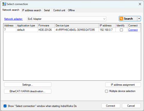
To connect with IndraWorks Ds:
-
Setup and start the EoE Tunnel as described above.
-
Open IndraWorks Ds.
-
On the toolbar, click the Select the connection  button.
-
In the Select connection dialog, in the Network Adapter box, select EoE Adapter.
-
Once the valve appears in the list, click Connect.
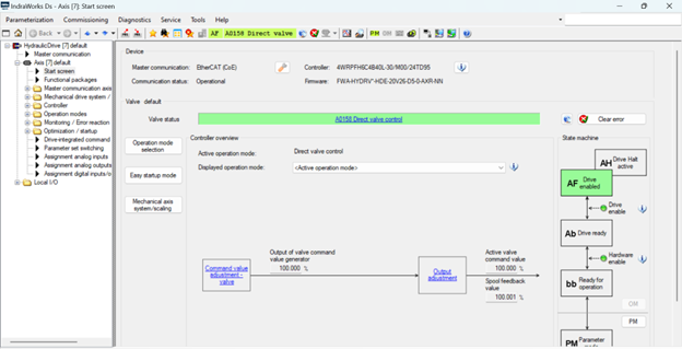
The main screen shows the valve state, whether it is ready, enabled, etc.
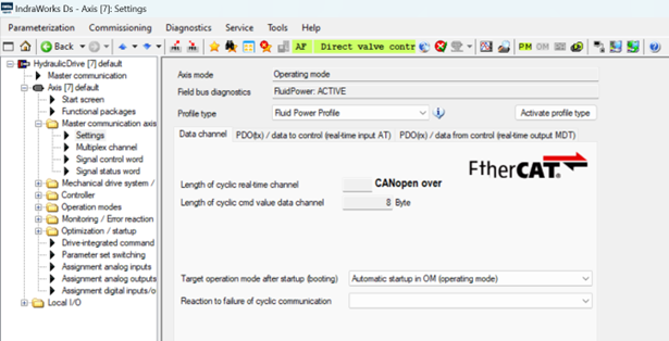
Expand Master Communication Axis, then select Settings to view the Profile Type, which must be Fluid Power Profile (the INIT commands configure this).
See Also
Using Valves with EtherCAT | EtherCAT Overview
Send comments on this topic.
Copyright © 2025 Delta Computer Systems, Inc. dba Delta Motion