The RMC supports EtherCAT hydraulic valves conforming to the CiA408 valve profile. This topic provides an overview of the main features related to using EtherCAT valves along with general instructions for configuring an RMC to use an EtherCAT valve.
Manufacturer-specific Instructions
For detailed instructions on using specific valves, see:
Typical Configuration
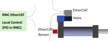
In RMC applications, an EtherCAT hydraulic valve is typically used as part of an axis that receives the position (and pressure or force for dual-loop axes) from a separate device, which may or may not be via EtherCAT.
The RMC axis receives feedback from the sensors and sends a Control Output signal (usually +/-100%) to the valve. The valve internally controls the spool position to match the Control Output signal. The RMC performs the position and pressure or force PID calculations as a normal axis.
Spool Position Closed-Loop Control Valve Mode
The valve mode in this typical configuration, where the Control Output signal commands the spool position, is referred to in various ways, such as spool position closed-loop control, flow control closed loop, or Q control closed loop.
The CiA408 specification defines the valve control mode in the CoE object Device Control Mode (0x6043).
Typically, the RMC will use EtherCAT valves in the spool position control closed-loop mode, which is a value of 2 in the object Device Control Mode (0x6043).
Using Valves in Other Modes
Some EtherCAT valves support other modes, such as pressure and flow control, active damping, or on-board axis controllers (where the position and pressure sensors are wired directly to the valve and the valve performs the motion control). Typically, these other modes are not used with the RMC, because the RMC has this functionality. However, advanced users may wish to use such functionality. This involves setting the Device Control Mode (0x6043) to the correct value and possibly changing other settings, such as the PDO mapping. Refer to the valve manufacturer’s documentation for details.
Axis Definitions
When defining an axis that includes an EtherCAT valve, pay attention to the following items:
Valve States
The RMC200 Valve State axis status register displays the state of the drive.
Control Mode
For axes with EtherCAT valves, choose Local Control (Main PID in RMC).
Output
When defining an axis that uses an EtherCAT valve, the axis’ Output is always to a Valve.
Feedback
For axes using EtherCAT valves, configure the feedback as required, whether single or dual loop, and via EtherCAT or via an RMC I/O module.
CiA408 valve states are:
NotReady
Init
Disabled
Hold
Active
FaultInit
FaultDisabled
FaultHold
FaultReaction
The RMC200 handles changing the state of the valve when an axis is enabled and disabled. The valve must be in the Active state in order to operate.
These valve states are separate from EtherCAT communication states. However, a valve will not allow operation if the drive’s EtherCAT state is not Op Mode.
For more details, see the Valve State axis status register.
Axis Status and Parameter Registers
The following Axis Status and Parameter registers are of particular importance for EtherCAT valves:
This Axis Status register is the actual value that is sent to the valve to command the spool position. The range is usually -16,384 to 16,384 or -100,000 to 100,000.
This Axis Parameter defines whether the valve receives a unidirectional or bidirectional signal. Typically, this should be bidirectional, indicating the signal is ±100%.
Output at 100%, Output at 0%, Output at -100%
These Axis Parameters scale the Control Output to the Final Output, which is sent to the valve. These parameters will typically be -16,384, 0 and 16,384, or -100,000, 0 and 100,000.
This Axis Parameter specifies the address in the valve to which the Final Output is sent. The Setpoint Index Axis Parameter should typically be set to 0x6300:01.
Control Word Index and Status Word Index
These Axis Parameters specify the address in the valve of the Control Word and Status Word. The Control Word and Status Word are used to control the valve state. These parameters should typically be 0x6040:00 and 0x6041:00.
Important CoE Objects for Valves
The CoE objects listed below are important for CiA408 EtherCAT valves. Some valves come with these objects set to the correct values to operate via EtherCAT while others require configuration, either via the valve software or via Init commands.
Device Mode (0x6042)
This should be a value of 1 to specify that the setpoint command is via EtherCAT. A value of 2 indicates the valve will use its analog input for the setpoint command and will ignore the command received via EtherCAT.
Device Control Mode (0x6043)
Typically, this should be set to 2, for spool position control closed-loop mode.
Device local (0x604F)
This should be set to 0 to indicate that the Control Word source is via EtherCAT. A value of 1 indicates the valve will use local control (internal to the valve) and will ignore the Control Word data received via EtherCAT.
Setting up EtherCAT Valves
To set up an axis with an EtherCAT valve:
Create the Axis
When creating an axis in the RMC, in the New Axis Wizard, choose a Control Axis, then choose Local Control (Main PID in RMC).
Configure PDO Data
Configure the EtherCAT PDO data for the SubDevice so that it includes:
Input data:
Status Word (0x6041:00)
Spool actual value (0x6301:01)
Output data:
Control Word (0x6040:00)
Spool set value (0x6300:01)
Note that the Spool Actual Value is not strictly required but can be useful for troubleshooting.
Create Init Commands
Some valves may require Init commands so that the valve will be in the correct control mode and will use the EtherCAT signal as a command. For details, see the instructions for a specific valve listed at the top of this topic.
Axis Parameters - Output
Configure the following output Axis Parameters:
Output SubDevice: select the valve
Control Word Index: 0x6040:00
Status Word Index: 0x6041:00
Output Type: Set to Counts Bi (for a typical 4-way valve)
If the valve is 3-way, set to Counts Uni.
Output at 100%, Output at 0%, Output at -100%:
Set according to the valve manufacturer documentation:
| Output at 100% | Output at 0% | Output at -100% | |
|---|---|---|---|
| ATOS | 16,384* | 0 | -16,384* |
| Bosche | 100,000 | 0 | -100,000 |
| Moog | 16,384 | 0 | -16,384 |
| Parker | 16,384 | 0 | -16,384 |
*ATOS can support 100,000 to -100,000 if the VDMA version is changed from 1.5 to 1.6 using the ATOS configuration software, or setting the ATOS-specific object 0x220D.
Scaling the Feedback
Configure and scale the position and/or pressure or force feedback as usual.
Tuning
Tune the axis as usual.
See Also
EtherCAT Overview | EtherCAT 3rd Party Overview
Copyright © 2026 Delta Computer Systems, Inc. dba Delta Motion