|
Type: |
|
|
Address: |
RMC75: %MDn.42, where n = 12 + the axis number RMC150: %MDn.42, where n = 24 + the axis number RMC200: %MDn.152, where n = 384 + the axis number |
|
System Tag: |
|
|
How to Find: |
Axes Parameters Pane, All tab: Output |
|
Data Type: |
|
|
Units: |
RMC75/150: V RMC200: % |
|
Range: |
RMC75/150: 0 to 10 V RMC200: 0 to 100 % |
|
Default Value: |
0 (disabled) |
Description
The Output Deadband is the amount added or subtracted from the Control Output to compensate for a "deadband" in the system. Valves with overlapped spools, and some drives do not react to small changes in output; this effect is termed "dead band". Deadband compensation can be performed in closed-loop control only. No deadband compensation is performed in open-loop control.
The Output Deadband works together with the Deadband Tolerance parameter. These are essential tuning parameters if the system exhibits a deadband. Care must be taken to not make this value too large or the axis may oscillate. Normally, the Output Deadband value can be determined from the valve datasheet, which indicates how large the overlap is.
Many systems do not require any deadband compensation.
How it Works
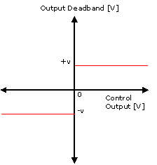
The Output Deadband is added to or subtracted from the Control Output (depending on its sign) so that the Control Output is outside the dead band.
If the Control Output is positive, the Output Deadband (v) is added to the Control Output.
If the Control Output is negative, the Output Deadband (v) is subtracted from the Control Output.
The Output Deadband also works together with the following components:
Deadband Tolerance parameter
If the Position Error is less than the Deadband Tolerance, then only a fraction of the Control Output, proportional to the Position Error, is applied. This helps keep the axis from chattering. See the Deadband Tolerance topic for details.
The Deadband Tolerance has no effect in Velocity PID or Velocity I-PD control. The Deadband Output is applied based on the direction, but always at 100% in one direction or the other.
Integrator
The Output Deadband also affects the functionality of the Integral Term. If the target is stopped and the position error is less than the Deadband Tolerance window or less than the position corresponding to one half of a transducer Raw Count, then the integrator is only allowed to wind down. This reduces "hunting". See the Integral Term and Integral Gain topics for more details.
Determining the Output Deadband
Follow these steps to determine what the Output Deadband should be set to:
Give increasing amounts of Control Output to the system with the Direct Output (9) command until the system starts to move. Start with a Requested Output of 0 V. The value of Control Output at which the system starts to move is your deadband.
If the deadband is less than a few hundred millivolts (approx. 0.4V), your system probably does not need the deadband eliminator. Set the Output Deadband to 0.
If the deadband is greater than a few hundred millivolts (approx. 0.4V), you probably need the deadband eliminator. Set the Output Deadband to the value of your deadband.
Control Modes
The Deadband compensation applies to all the closed-loop control modes: Position PID, Position I-PD, Velocity PID, Velocity I-PD.
Velocity Control
The Output Deadband applies to velocity control axes. If the Deadband Tolerance value is non-zero, then the Output Deadband will not apply if the Target Pressure or Velocity is zero. Otherwise, the value of the Deadband Tolerance has no meaning.
Pressure/Force Control
The Output Deadband applies to pressure/force control. If the Deadband Tolerance value is non-zero, then the Output Deadband will not apply if the Target Pressure or Target Force is zero. Otherwise, the value of the Deadband Tolerance has no meaning.
Pressure/Force Limit on Position-Pressure or Position-Force Axes
The Output Deadband is applied as normal, based on position. The Deadband Tolerance is applied based on the position as normal. Notice that if the axis is pressure/force limited, the position may be outside the tolerance window, and the full compensation will apply.
The Deadband Tolerance controls the integrator for the position component. If the target is stopped and the position error is less than the window then the position of the integrator is only allowed to wind down. When the axis is pressure/force limited then the position integrator is not used and the Deadband Tolerance has no effect.
Why Bother?
On an axis with overlapped spools or a large amount of static friction, the axis may oscillate slowly around the Command Position. This happens when the axis does not respond to small changes in Control Output. The integrator winds up until the axis moves and then has too much Control Output, overshooting the Command Position. The axis then winds the integrator down until the axis overshoots the other way.
If this happens, look at the Control Output. The Control Output will oscillate slowly as the axis oscillates. Notice the peak-to-peak values of the Control Output oscillation and subtract the minimum value from the maximum value and then divide the result by two. Enter this value in the Output Deadband register as a starting point.
A spool that has 10% overlap will require a value of about 1 Volt.
See Also
Parameter Registers | Deadband Tolerance
Copyright © 2025 Delta Computer Systems, Inc. dba Delta Motion