Open topic with navigation
Using Logix Designer Export Components
This topic explains how to use the communication data tags and example ladder logic generated by the RMCTools' Logix Designer Export feature. This is only available for the Rockwell Studio 5000 Logix Designer.
The EtherNet/IP cyclic I/O data can be difficult to decipher and use. The exported tags and logic from RMCTools are designed to make the data easy to read and simplifies the logic for the user.
How to Export and Import
Before starting:
-
Configure the EtherNet/IP connection in RMCTools as described in Using Allen-Bradley Controllers via EtherNet/IP I/O.
-
Make sure to have the following information:
-
The name of the RMC as used in your Logix Designer project. The name must be less than 32 characters, but may need to be even shorter, as explained in item 3 below.
-
If using the RMC200, the number of I/O connections.
-
The number of PLC Input Data registers.
-
The number of PLC Output Data registers.
-
Logix Designer limits the length of imported tag names. This means the lengths of the RMC name, axis names and variable tag names must limited such that any tag does not exceed 40 characters. For example, the exported Axis 0 Status Bits tag name is MyRMCNameMyAxisNameStatusBits and the Axis 0 Command Parameter 1 is MyAxisName_Command_Parameter_1. The wizard allows you to preview the tags to be exported.
To export from RMCTools to a Logix Designer Export/Import file:
-
In the RMCTools Project pane, expand the Modules folder.
-
Double-click the CPU module, and choose the EtherNet/IP page.
-
In the Logix Designer Export section, click Export to Logix Designer.
-
Complete the Logix Designer Export wizard. It will prompt you to save an .L5X file.
To import the .L5X file to Logix Designer:
-
In Logix Designer, in a ladder logic routine, right-click a rung and choose Import Rungs.
-
Browse to the .L5X file and click Open.
-
In the Import Configuration dialog, click OK (if you are re-importing a modified file, see Re-importing Logic below).
Imported Components
The following components are imported into Logix Designer:
|
Controller Tags:
One each of the following per connection:
-
Input
Data Tag (in the example, MyRMCIn1)
Contains all the tags for the input data coming from the RMC.
This tag uses a special user-defined data type (MyRMC_IN_DATA1).
See User-Defined Data Types
below.
-
Output
Data Tag (in the example, MyRMCOut1)
Contains all the tags for the output data going to the RMC.
The data type is an imported user-defined data type. This
tag uses a special user-defined data type (MyRMC_OUT_DATA1).
See User-Defined Data Types
below.
-
Send
Request bit (in the example, MyRMCSndReq1)
Used to apply the output data to the RMC. First it copies the
output data to the output buffer. If the Sync Register is
used, it then changes the sync register to trigger the RMC
to apply the data.
-
Busy
bit (in the example, MyRMCBusy1)
Indicates that the Sync Register write transaction is in process.
This bit is included only if the connection uses the Sync
Register.
|
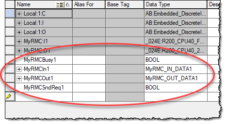
Example:
The tags circled in the image below are imported for an RMC with the module name MyRMC.
|
Ladder Logic
One rung is imported
for copying input data. If multiple connections are used, the rung uses
multiple branches for each connection. See Input
Data Logic below for details.
If the connection uses a Sync Register, two rungs per connection are imported for copying output data and managing the Sync register. See Output Data Logic With a Sync Register below for details.
If the connection does not use a Sync Register, one rung per connection is imported for applying output data. See Output Data Logic Without a Sync Register below for details.
User-Defined Data Types:
These user-defined data types (UDTs) are applied to the imported input and output tags. All the UDTs are prefaced by the module name of the RMC as used in Logix Designer.
-
RMCname_IN_DATA
Input data type
-
RMCname_OUT_DATA
Output data type
-
RMCname_axisnameStatusBits
Axis Status Bits data types. Only if Axis Status Bits registers are included in the input data. One Status Bits data type per axis will be created, since the valid status bits may vary between axes.
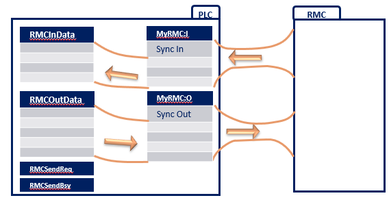
The imported data tags and the data flow can be visualized as follows:
Input Data Logic
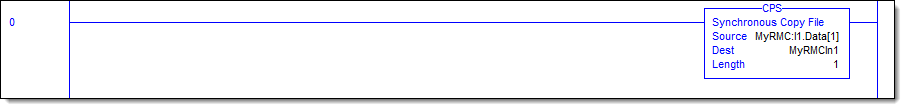
The input data rung continuously copies the difficult-to-decipher EtherNet/IP input data array MyRMC:I1.Data to the easy-to-read input tag MyRMCIn1.
This example was generated for an RMC with the module name MyRMC, using a connection with a Sync Register. The Sync Register at index 0 in the array. The copy starts at index 1, not index 0, because the Sync Register at index 0 need not be copied to the input tag. If the connection did not use the Sync Register, the copy would start at index 0.
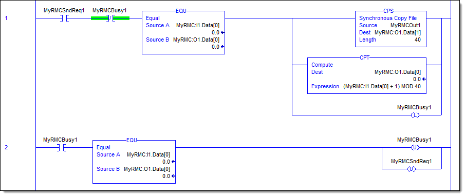
Output Data Logic With a Sync Register
When the RMC EtherNet/IP connection has been set to use the Sync Register, two rungs are imported to handle the output data going to the RMC.
The two rungs work together to apply data to the RMC and keep the communications synchronized with the Sync Register. The first rung copies the data and increments the Sync Register to trigger the RMC to apply the data. The second rung waits for the Sync Register value to be echoed by the RMC, to ensure that the data was applied to the RMC before releasing control.
When using these rungs in an application, the PLC must do the following to apply data to the RMC:
-
Set the desired values in the output tag.
-
Set the Send Request bit.
When the Send Request bit and Send Busy bits clear, the data has been applied to the RMC. This indicates that the transaction is complete, and any PLC logic depending on it can now proceed.
The following rung analysis applies to the example ladder logic below, which was generated for an RMC with the module name MyRMC.
First Rung Details
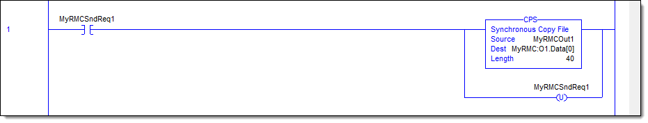
When the Send Request bit (MyRMCSndReq1) is set, the first rung copies the easy-to-read output tag MyRMCOut1 to the difficult-to-decipher EtherNet/IP output data array MyRMC:O1.Data. It does so by performing these steps:
-
Checks to make sure the Busy bit is not set, which means a previous transaction is still in process.
-
Waits for the SyncIn and SyncOut registers to be equal. If they are not equal, that means a previous transaction is still in process.
-
Copies the easy-to-read output tag MyRMCOut1 to the difficult-to-decipher EtherNet/IP output data array MyRMC:O1.Data. The copy starts at index 1, not index 0, because the Sync Register at index 0 need not be copied to the input tag.
-
Changes the SyncOut register by adding 1 to it. It uses a modulo so that the value does not increase beyond its valid range.
-
Latches the Busy bit.
Second Rung Details
When the Busy bit MyRMCBusy1) is set, the second rung ensures that the data was applied to the RMC before releasing control. It does so by performing these steps:
Output Data Logic Without a Sync Register
When the RMC EtherNet/IP connection has been set to not use the Sync Register, one rung is imported to handle the output data going to the RMC.
On the rising edge of the Send Request bit, the output rung copies the easy-to-read output tag MyRMCOut1 to the difficult-to-decipher EtherNet/IP output data array MyRMC:O1.Data.
When using this rung in an application, the PLC must do the following each time the data is to be applied to the RMC:
-
Set the desired values in the output tag.
-
Set the Send Request bit.
The Send Request bit will clear as soon as the copy is complete. Without a Sync register, there is no indication from the RMC to know when the data was actually applied. The user should take care in programming the PLC logic to account for this.
This example was generated for an RMC with the module name MyRMC. This example does not use the Sync Register.
Re-importing Logic
If you change the EtherNet/IP data tags in the RMC after initially exporting tags and ladder logic, you can re-import the logic to Logix Designer. In the Logix Designer Import Configuration dialog, you must specifically select which imported tags you want to overwrite the existing tags. The Import Configuration dialog defaults to use the existing Logix Designer tags, not the imported tags. When changing data, you will need to re-import both tags and the user-defined data types. If you change the data length, you will need to make sure to change the data lengths both in RMCTools before exporting, and in the defined RMC module in Logix Designer.
Example
If you change some tag names in the RMC, you may wish to import and overwrite the tags in Logix Designer, but not overwrite the ladder logic rungs. You would do the following:
-
In Logix Designer, in a ladder logic routine, right-click a rung and choose Import Rungs.
-
Browse to the .L5X file and click Open.
-
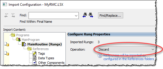
In the Import Configuration dialog, in the Import Content box, choose Main Routine.
-
In the Operation box, choose Discard.
-
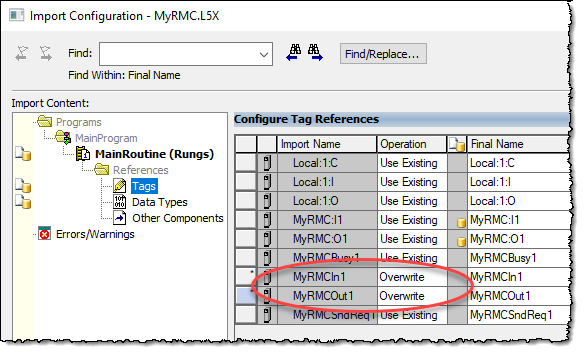
In the Import Content box, choose Tags.
-
For the tags you wish to use (typically the In tag and the Out tags), choose Overwrite.
-
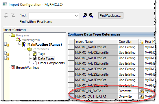
In the Import Content box, choose Data Types.
-
For the data types you wish to use (typically the In tag and the Out datatypes), choose Overwrite.
-
Click OK to import the selected items.
See Also
Using Allen-Bradley Controllers via EtherNet/IP I/O
Send comments on this topic.
Copyright © 2026 Delta Computer Systems, Inc. dba Delta Motion