RMCTools can connect to the RMC75, RMC150, and RMC200 motion controllers over Ethernet using a CIP Bridge. A CIP Bridge refers to a device—such as a ControlLogix PLC—that routes Common Industrial Protocol (CIP) communications between two different Ethernet networks. This creates a bridge that allows communication between devices on separate subnets.
CIP (Common Industrial Protocol) is a widely used application-layer protocol in industrial automation. CIP is used by several industrial network protocols, including EtherNet/IP and DeviceNet. RMCTools supports CIP and can communicate through CIP Bridges to reach RMC controllers located on different networks.
Segregated Networks
In many factories, the main plant network is separated from individual machine networks. For example, the PLC on a machine may communicate with the main plant network via an Ethernet module on the PLC and communicate to a smaller network on the machine via a different Ethernet module on the PLC. This separation of networks reduces network traffic and improves security.
A CIP Bridge allows RMCTools to be used in the plant control room, connected only to the main plant network, and communicate to an RMC on a separate network by bridging through a Rockwell PLC, such as ControlLogix or CompactLogix.
A CIP Bridge is typically made through one PLC, although it is possible to bridge through multiple PLCs or devices.
CIP Routing Path
To communicate with an RMC, a CIP Routing Path must be entered in the Connection Path dialog, which defines the route taken by CIP communications. It is given as a mix of IP addresses and numbers. The path is created from the perspective of starting at the PC that is running RMCTools.
A routing path through a single PLC is typically built as follows:
IP Address of First Device
The IP address of the first device that the PC running RMCTools connects to. This is usually an Ethernet module in a ControlLogix.
Numbers to represent backplane and/or ports
The number or numbers represent how the communications are routed inside the PLC, such as to the backplane and then to a certain slot number of a different Ethernet module in the PLC, or directly to another Ethernet port on the first Ethernet module.
IP address of RMC
The IP address of the RMC.
ControlLogix CIP Routing Path – Single PLC
To route RMCTools to RMC communications through one ControlLogix PLC, the CIP routing path follows this format:
[IP address 1], 1, [slot number], [Communication Port], [IP address of RMC]
The routing path components are:
IP address 1:
The IP address of the Ethernet module in the PLC that is connected to the same network as the PC running RMCTools.
1:
Indicates connection from the PLC’s Ethernet module to the backplane.
Slot number:
The slot number in the PLC of the Ethernet module that is connected to the same network as the RMC.
Communication Port:
Specifies which port to use on the PLC’s Ethernet module. Typically this is 2, which indicates Ethernet.
IP address of RMC
The IP address of the RMC. Note that this is a separate network than the network connected to the PC running RMCTools.
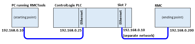
For example, consider this setup:
The CIP routing path is:
192.168.0.25, 1, 7, 2, 192.168.0.200
Where:
1= backplane
7= slot number
2= Ethernet
CompactLogix CIP Routing Path – Single PLC
At the time of this writing (2025), the only CompactLogix PLC (and GuardLogix) that supports CIP Bridging is the 5380 series.
The CompactLogix must first be configured to operate in Dual-IP mode. This allows the two Ethernet ports, port A1 and port A2, to be connected to separate networks. A limitation is that the network addresses of the two networks must be on separate subnets. Refer to Rockwell documentation for details.
To route RMCTools to RMC communications through one CompactLogix PLC, the CIP Routing Path is created as follows:
[IP address 1], [Communication Port], [IP address of RMC]
IP address 1:
The IP address of the Ethernet module in the PLC that is connected to the same network as the PC running RMCTools.
Communication Port:
For port A1: 3
For port A2: 4
IP address of RMC
The IP address of the RMC. Note that this is a separate network than the network connected to the PC running RMCTools. The CompactLogix Dual-IP mode requires that the address ranges of each network do not overlap.
For example, consider this setup:
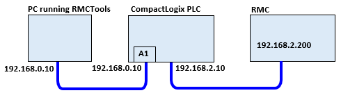
The CIP routing path is:
192.168.0.10, 4, 192.168.2.200
Where:
4 = port A2
CIP Routing through Multiple PLCs
CIP communications can be routed through multiple PLCs. To do so, the paths are formed similarly as described above, with the next value in the path describing the next place in the route.
For example, consider routing through two ControlLogix PLCs, where the IP are as follows:
PC running RMCTools:
IP address: 192.168.1.30
First ControlLogix:
Ethernet module 1: slot 2, IP address 192.168.1.20
Ethernet module 2: slot 4, IP address 192.168.2.20
Second ControlLogix:
Ethernet module 1: slot 5, IP address 192.168.2.21
Ethernet module 2: slot 6, IP address 192.168.3.50
RMC:
IP address: 192.168.3.150
The CIP path would be:
192.168.1.20, 1, 4, 2, 192.168.2.21, 1, 6, 2, 192.168.3.50
See Also
CIP Bridge Settings | Connection Path
Copyright © 2026 Delta Computer Systems, Inc. dba Delta Motion