Legend
— Master Position
— Slave Position
— Slave Velocity
— Master Velocity
The master positions are indicated on the x-axis for clarity, although the positions are actually on the y-axis.
|
Supported Axes: |
Position Control Axes |
|
Supported Control Modes: |
See the Commands Overview topic for basic command information and how to issue commands from PLCs, HMIs, etc.
Command Parameters
|
# |
Parameter Description |
Range |
|---|---|---|
|
1 |
Final Gear Ratio |
Any REAL number |
|
2 |
Master Register Note: See Specifying a Register Address below. |
Valid RMC register |
|
3 |
Master Sync Position (position-units) |
Any REAL number |
|
4 |
Slave Sync Position (position-units) |
Any REAL number |
|
5 |
Master Start Distance (position-units) |
Any REAL number |
|
6 |
Master Direction If the master axis linear, this should be Nearest (0). The other options will have no effect. If the master axis is rotary, see the Rotary Motion section below. |
a valid integer as described |
|
7 |
Slave Direction If the slave axis linear, this must be Nearest (0). The other options will have no effect. If the slave axis is rotary, see the Rotary Motion section below. |
a valid integer as described |
Description
This command electronically gears the axis to the requested register such that the two axes synchronize exactly at the requested Master Sync Position and Slave Sync Position and then remain geared at the specified Final Gear Ratio. Typically, the master register is the Target or Actual Position of another axis. This command is intended for use in flying-cutoff and flying-shear type applications. This command will work even if the speed of the master is changing.
See the Gearing Overview topic for general information about gearing, including Gear Ratio, Clutching and possible Gear Masters.
Definitions
The plot below is typical of a Gear Pos (Clutch by Distance) command. The table below uses the plot to define some important concepts used in the remaining discussion.
|
|
Legend
— Master Position — Slave Position — Slave Velocity — Master Velocity
The master positions are indicated on the x-axis for clarity, although the positions are actually on the y-axis. |
|
Term |
Description |
|
Master Sync Position |
The position of the master at which the slave will be at its sync position and will be at locked in at the final gear ratio. |
|
Master Start Distance |
The distance from the Master Sync Position during which the clutching will take place. This area is also called the "clutch area". Note: This is the distance, not the absolute position! |
|
Master Start Position |
The master position at which the slave starts clutching. This position is Master Sync Position - Master Start Distance. |
|
Slave Sync Position |
The position of the slave at which the master will be at its sync position and the slave will be at locked in at the final gear ratio. |
|
Slave Start Position |
The slave position at the time the command is issued. |
|
Slave Distance |
The distance between the Slave Start Position and the Slave Sync Position. |
Clutching
This command requires that the slave is either stopped (which is a zero gear ratio) or geared when the command is issued. This gear ratio will be used to create an initial constant gear ratio that holds until the master reaches the Master Start Position.
When the master moves beyond the Master Start Position, the gear ratio will ramped from the initial ratio to the requested ratio such that the two synchronize exactly at the requested Master Sync Position and Slave Sync Position. The Master Start Distance specifies how far from the Master Sync Position the clutching should start.
The Master Start Distance implies the direction with its sign. For example, with a Master Sync Position of 10, a Master Start Distance of 2 means that the clutching happens as the master moves from 8 up to 10. With a Master Sync Position of 10, a Master Start Distance of -2 means that the clutching happens from 12 down to 10.
Notice that the RMCwill decrease the Master Start Distance in some cases. See the Master Start Distance Details section below for more details.
Reversing Direction
This command allows reversing the direction of the master. If the master reverses directions before the axes have reached the sync positions, the slave will follow the profile in reverse. If the master continues in reverse past the Master Start Distance, the slave will continue following the master in reverse using the initial gear ratio. The clutching will resume if the master returns to the Master Start Position.
Once the axes have reached the sync positions, the slave will lock in at the final gear ratio, and will gear to the master at that ratio whether the master goes forward or backward. It will not revert to the profile it followed before reaching the sync position.
Errors
If the axis is not stopped or already geared when this command is issued, a Command Error will be generated.
If the Master Position is already beyond the Master Sync Position when the command is issued (where "beyond" is defined by the direction implied by the Master Start Distance as described above), then the command will fail with a Command Error.
If the Master Position is already in the clutch area (between Master Start Position and Master Sync Position) when the command is issued, then the command will proceed but with a Command Modified error, since the effective Master Start Distance will be adjusted to make the move complete. Setting the Command Modified Auto Stop to Status Only will allow this move to proceed.
Uses for Gear Pos (Clutch by Distance) Command
The Gear Pos (Clutch by Distance) command is useful for the following purposes:
Flying-Cutoff
This command is designed for flying-cutoff or flying-shear type applications. See the example below for more details.
"Superimposed" Move
If an axis is already geared to a master, this command can be used to make a "superimposed" move on the slave. To do this, issue this command with the same final gear ratio that the axis was already geared with. See the Gear Ratio Details
section below for caveats. Notice that the RMC has other gearing commands intended for this purpose that may work better, such as Geared Slave Offset (35) and Phasing (34).
Stop Based on Master Position
If an axis is already geared, this command can be used to stop an axis based on the position of the master. Use a final gear ratio of zero. This guarantees that the slave will stop at the right position relative to the master.
Point-to-Point Move Based on Master Position
If an axis is stopped, this command can be used to do a point-to-point move on the axis based on the position of the master. Use a final gear ratio of zero. The axis will start moving as described in the Master Start Distance Details Below and will stop at the specified sync positions.
Flying-Cutoff Example
Consider this flying-cutoff example. A belt is moving a continuous pipe, which is to be cut to length while the belt is moving. The saw is mounted on a carriage that can speed up to the speed of the belt, and then it can make the cut. After cutting, the carriage returns to the home position.
The belt (the master) is controlled by Axis 1 with a rotary encoder, moving at 5 inches/second. The carriage (the slave) is controlled by Axis 0. The carriage will start at and return to a home position of zero(0). The cut should take place when the master is at 12 in. and the slave is at 10 in and locked at a 1:1 ratio. The slave must be synchronized at 8 inches (2 inches before the cut). Therefore, the Slave Sync Position will be 8 and the Master Sync Position will be 10.
The Master Start Distance should be set to allow the slave time to get to speed. Because we will issue the command after the master crosses zero, we will set the Master Start Position greater than zero (0). We will use a Master Start Distance 9, resulting in a Master Start Position of 1.
The parameters of the Gear Position (Clutch by Distance) command are as listed below:
Final Gear Ratio = 1.0
Master Register = F9:53 (Axis 1 Target Position)
Master Sync Position = 10 inches
Slave Sync Position = 8 inches
Master Start Distance = 9 inches
The plot of this motion is shown below. This plot also includes the motion of the carriage moving back (beginning at approximately 3.5 sec) after it has finished cutting.
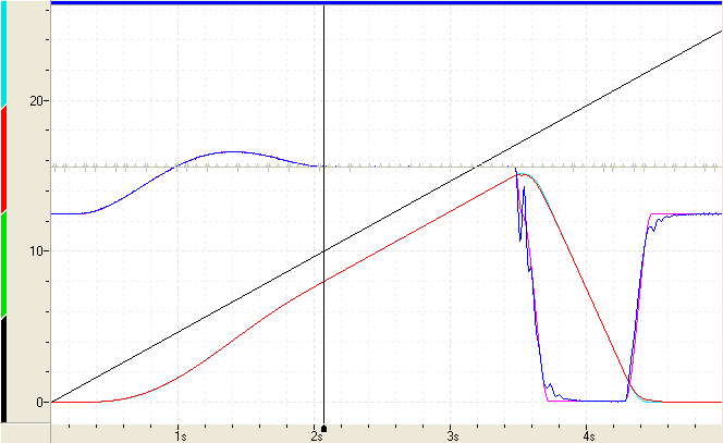
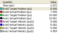
The plot shows Axis 1 (the master) moving at a constant 5 in/sec. The carriage (Axis 0) is stopped, then accelerates to catch up to the master. Axis 0 and Axis 1 Target Positions are synchronized at 8 and 10, as indicated by the legend to the right. The legend indicates the values at the cursor in the plot. In the plot, the axes remain synchronized (while the system is cutting) until approximately 3.5 seconds, at which point a command was issued to move the carriage back to its home position. This return move can be done with a Move Absolute, or even the Gear Pos (Clutch by Distance) command. | Plot Legend
|
Master Start Distance Details
The Master Start Distance specifies how far from the Master Sync Position the clutching should start. This position is called the Master Start Position. When the master reaches this position, the slave axis begins moving. This section describes how the Master Start Distance affects the motion and cases in which the RMC modifies the Master Start Distance.
If the Slave is Initially Stopped or Geared at a Zero Ratio
The distance from the Slave Start Position (slave position at the time the command is issued) to the Slave Sync Position is called the Slave Distance. If the slave is stopped or geared at a ratio of zero when this command is issued, and the Master Start Distance is greater than (2.5 x Slave Distance / Final Gear Ratio), then the Master Start Distance will be reduced to (2.5 x Slave Distance / Final Ratio). This behavior is due to the mathematical formula used to calculate the profile. Without this behavior, the profile might move in the wrong direction first. Notice that after the command is issued, the slave will remain stopped or geared at 0:1 until the master reaches the modified Master Start Position.
Example
Consider a Gear Pos (Clutch by Distance) command issued with the parameters listed below. The command is issued when the slave axis is stopped at 0. Therefore, the Slave Start Position is 0.
Ratio = 1
Master Sync Pos = 5
Slave Sync Pos = 1
Master Start Distance = 4
The Slave Distance = Slave Sync Position - Slave Start Position = 1 - 0 = 1.
Also, (2.5 x Slave Distance / Final Gear Ratio) = (2.5 x 1 / 1 ) = 2.5.
Therefore, the specified Master Start Distance of 4 is greater than 2.5 as calculated above and will be limited to 2.5.
The plot of the motion looks like this:
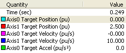
The legend to the right indicates the values at the cursor in the plot. The Gear Pos (Clutch by Distance) command was issued at the beginning of the plot. Notice that the slave begins moving when the master is at 2.5 (the Master Sync Pos - Master Start Distance = 5 - 2.5 = 2.5). Before that point, the slave continues at the initial ratio, which was 0:1. | Plot Legend
|
Important Master Start Distance Values
As discussed above, if the slave is initially stopped or geared at a ratio of zero, the Master Start Distance will be limited to (2.5 x Slave Distance / Final Gear Ratio). However, other values are also important. The ratio between the master and slave distances divides the behavior into four classes:
≥ 2.5 x Slave Distance / Final Gear Ratio
= 2.0 x Slave Distance / Final Gear Ratio
= 1.6666 x Slave Distance / Final Gear Ratio
< 1.6666 x Slave Distance / Final Gear Ratio
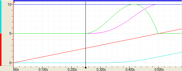
In the plots below, observe the slave velocity (magenta) and the slave acceleration (green) for each class listed above.
Master Start Distance ≥ 2.5 x Slave Distance / Final Gear Ratio

- Notice the smooth initial acceleration, but relatively high rate of acceleration at the sync position. This may cause minor difficulty tracking at the sync point.
Master Start Distance = 2.0 x Slave Distance / Final Gear Ratio
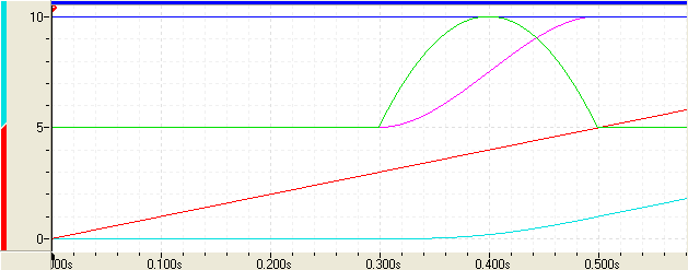
- Notice the symmetrical acceleration. There is still a relatively high rate of acceleration at the sync position, which may cause minor difficulty tracking at the sync point.
Master Start Distance = 1.6666 x Slave Distance / Final Gear Ratio

- Notice the sharp initial acceleration, but smooth rate of acceleration (due to zero jerk) at the sync position. This makes tracking easier at the sync point.
Master Start Distance < 1.6666 x Slave Distance / Final Gear Ratio
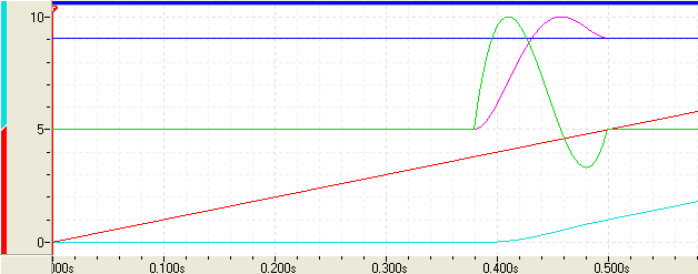
- Notice that the slave velocity increases above the master velocity in order to reach the sync position. This is acceptable or will be necessary in some applications.
If the Slave is not Initially Stopped
If the slave is not initially stopped when this command is issued, the Master Start Distance will not be truncated to 2.5 x Slave Distance / Final Gear Ratio. Therefore, the target profile may in some cases move in the other direction before moving in the direction of the master. Make sure to test the Gear Pos (Clutch by Distance) parameters you will be using to verify that the profiles are acceptable.
Gear Ratio Details
This command has only one register to specify the gear ratio. Therefore, it cannot exactly represent certain fractional numbers, such as 1/3. If you require such a ratio, first issue this command with the desired sync positions and an approximate final ratio, then issue the Gear Pos (Clutch by Time) (30) command after the axes have locked into the final gear ratio. Make sure to specify a time of zero (0) for the Gear Pos (Clutch by Time) command. To maintain accuracy, this should be done in a user program. Use the Target Generator Status bits to determine when the axes have locked in the final gear ratio. See the Target Generator State Bits section below.
The Gear Pos (Clutch by Distance) command will be accurate up to the sync positions. Therefore, you will not lose any accuracy by using the Gear Pos (Clutch by Distance) followed by a Gear Pos (Clutch by Time) command with a time of zero.
Specifying a Register Address
When issuing this command from anywhere other than RMCTools, the addresses in the Master Register command parameter must be entered as an integer value.
RMC addresses are represented in IEC format as:
%MDfile.element, where file = file number, and element = element number.
Use the following equation to convert a register address to integer format, N:
N = file * 4096 + element
Example:
Register address %MD8.33 is 8*4096 + 33 = 32801.
Rotary Motion
The Master Direction and Slave Direction parameters of this command are for use on rotary axes. For non-rotary axes, the direction parameters can only be "Nearest". The other options will have no effect. If the master register is not a Target Position or Actual Position register, the master directions cannot be rotary.
On rotary axes, the direction parameters specify the direction of the Slave Sync position from it's current position and the direction of the Master Start Distance from the Master Sync Position. See the Rotary Motion topic for details on the meaning of the direction options.
Direction Options
Negative (-1)
Nearest (0)
Positive (1)
Current (2)
Absolute (3)
Gearing Status
The Geared Status bit indicates whether the axis is currently actively following a master. It is set when an axis is currently geared to a master register and cleared when not geared. The Gear Master Register axis status register identifies the specific register location that the axis is currently following.
Target Generator State Bits
The Target Generator bits in the Status Bits register indicate which portion of the move the axis is currently in. These bits are useful when programming complex motion sequences.
Target Generator Done bit
Set when the master position is at or beyond the Master Sync Position. The gear ratio is now locked and will no longer change even if the master moves prior to the Master Sync Position.
Target Generator State A and B bits
B | A | Description |
|---|---|---|
0 | 0 | The master is beyond the Master Start Position. Use the Target Generator Done bit to determine if it has reached the Master Sync Position. |
0 | 1 | Reserved |
1 | 0 | The master is prior to the Master Start Position. |
1 | 1 | Reserved |
See Also
Gearing | List of Commands | Commands Overview
Copyright © 2026 Delta Computer Systems, Inc. dba Delta Motion