|
Firmware Limitations: |
RMC200: 1.25.0 or newer |
|
Hardware Limitations: |
Requires an EtherCAT MainDevice module |
See the Commands Overview topic for basic command information and how to issue commands from PLCs, HMIs, etc.
Command Parameters
|
# |
Parameter Description |
Range |
|---|---|---|
|
1 |
SubDevice The Station Address of the SubDevice. |
A valid integer between 0 and 65,535 |
|
2 |
Object Index The Address of the object in the SubDevice. This integer value represents both the Object Index and Object Subindex. See Object Index below. |
A valid integer between 1,048,576 (16#100000) and 16,777,215 (16#FFFFFF) |
|
3 |
Object Data Type Specifies the type of data being written. |
See Supported Object Data Types below |
|
4 |
Source Address of source register within the Variable Table. |
Valid Variable Table address |
|
5 |
Status Register Address of a DWORD variable in the Variable Table, which the RMC will update with the status of the CoE SDO Write. |
Valid Variable Table address |
Description
This command allows the user to write data to an EtherCAT SubDevice, using an SDO (Service Data Object) write. An SDO write transfers data only when specifically requested, as compared to a PDO that transfers data continuously. For reading from an EtherCAT object via SDO, see EtherCAT CoE SDO Read (123).
Timing Considerations
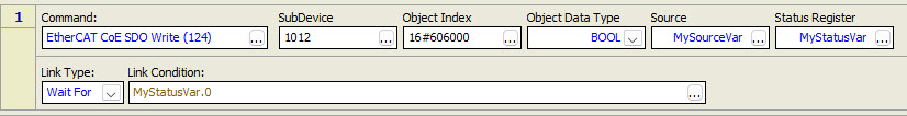
A CoE SDO Write takes multiple loop times to complete. Therefore, it may be important to verify that the write is complete before taking any action that depends on the write having completed. To verify the data is complete, check bit zero in the variable specified by the Status Register command parameter.
In the example user program below, the command writes from the variable MySourceVar to object 0x6060 (with subindex zero) in SubDevice 1012. The DWORD variable MyStatusVar is used as the Status Register. The Wait For Link Type waits for bit 0 of MyStatusVar to be true, which indicates that the write completed successfully, before continuing to the next user program step.
See Error Handling below for user program examples for handling errors.
Object Index
The Object Index command parameter specifies the address of the object to write to and includes both the Index and Subindex of the object. The Index and Subindex are listed in the CoE Object Dictionary for each object in an EtherCAT SubDevice.
The Object Index command parameter is typically entered in hexadecimal form, using either 16# or 0x as the prefix, followed by 6 hexadecimal characters, for example 16#607B01. The lowest two (rightmost) characters represent the SubIndex (1 byte), and the next four characters represent the Index (2 bytes). If represented as a 32-bit hexadecimal value, the left two characters (1 byte) must be zero, for example 16#00607B01.
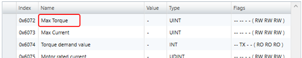
Example 1:
In the CoE Object Dictionary section given below, the object Max Torque has an Index value of 0x6072 and no Subindex, which means the Subindex is zero (0x00). Therefore, the Object Index command parameter is 16#607200.
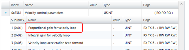
Example 2:
In the CoE Object Dictionary section given below, the object Proportional gain for velocity loop has an Index value of 0x2381 and a Subindex value of 0x01. Therefore, the Object Index command parameter is 16#238101.
More Examples:
The following Index and SubIndex values from the CoE Object Dictionary yield the Object Index command parameter value.
|
CoE Index |
0x7000 |
0x6061 |
0x1705 |
|
CoE Subindex |
0x10 |
0x00 |
0x0A |
|
Object Index Command Value |
16#700010 |
16#606100 |
16#17050A |
Note: In the CoE Object Dictionary, the SubIndex is given as both a decimal and hexadecimal (0xnn) value. Make sure to use the hexadecimal value when entering this command parameter as a hexadecimal value.
Object Data Types
The Object Data Type command parameter should be set to the data type of the object in the SubDevice. The table below lists the supported data types of objects in the SubDevice and which Variable Table data types can be used as a source in writes to the object data types. It also explains how the data will be applied to the SubDevice destination register.
In general, when the object data length is less than 32 bits, then the lower bits of the source variable is written into the Object.
Writing to arrays in a SubDevice is not supported.
Supported Object Data Types
The Variable Table data types DINT and DWORD can be interchanged depending on use case.
|
Value (INT) |
Object Data Type |
Bit Length |
Supported Variable Table Data Type |
Notes |
|---|---|---|---|---|
|
1 |
BOOL |
1 |
DWORD |
Will truncate high bits. |
|
2 |
SINT |
8 |
DINT |
Will truncate high bits. |
|
3 |
INT |
16 |
DINT |
Will truncate high bits. |
|
4 |
DINT |
32 |
DINT |
Maps directly. |
|
5 |
USINT |
8 |
DINT |
Will truncate high bits. |
|
6 |
UINT |
16 |
DINT |
Will truncate high bits. |
|
7 |
UDINT |
32 |
DINT |
Maps directly. |
|
8 |
REAL |
32 |
REAL |
Maps directly. |
|
17 |
LREAL |
64 |
REAL |
Maps directly. |
|
21 |
LINT |
64 |
DWORD |
Will use 2 consecutive variables in the Variable Table to write to LINT. The first variable will apply to the low 32 bits of the LINT in the destination register, and the second variable will apply to the high 32 bits in the destination register. |
|
27 |
ULINT |
64 |
DWORD |
Will use 2 consecutive variables in the Variable Table to write to ULINT. The first variable will apply to the low 32 bits of the LINT in the destination register, and the second variable will apply to the high 32 bits in the destination register. |
|
30 |
BYTE |
8 |
DWORD |
Will truncate high bits. |
|
31 |
WORD |
16 |
DWORD |
Will truncate high bits. |
|
32 |
DWORD |
32 |
DWORD |
Maps directly. |
Status Register
Select a DWORD variable in the Variable Table to act as a status register for this command. The following table describes the status bits that are returned into the variable specified by the Status Register after sending this command. After sending a write command, either the Done bit or Error bit will be set. If the Error bit is set, bits 2-12 indicate the specific error that occurred. The Event Log reports any errors that occur.
|
Status Register |
Name |
Description |
|
Bit 0 |
Done bit |
Set to Off when command is issued. Set to On when the command completes successfully. |
|
Bit 1 |
Error bit |
Set to Off when command is issued. Set to On when an error condition occurs. |
|
Bit 2 |
Invalid command parameter |
Valid command parameters are: Station Address must be between 1 and 65535 (inclusive). Object Index must be between 0x100000 and 0xFFFFFF. Data Type must be in the supported value list. Source or Destination must be a variable table address. The Status Register must be a variable table address. |
|
Bit 3 |
SubDevice was not found |
Station Address must be a SubDevice on the network. |
|
Bit 4 |
Object index is invalid |
The Index portion of the Object Index command parameter must be valid for the SubDevice. |
|
Bit 5 |
Object subindex is invalid |
The Subindex portion of the Object Index command parameter must be valid for the SubDevice. |
|
Bit 6 |
Object data type length mismatch |
The Object Data Type command parameter length must match the length of the object in the SubDevice. |
|
Bit 7 |
Object access type is write-only |
Object must have a read access type for read commands. |
|
Bit 8 |
Object access type is read-only |
Object must have a write access type for write commands. |
|
Bit 9 |
Object data value is invalid |
Some Objects have limited allowed values during write. |
|
Bit 10 |
CoE SDO request timed out |
This error can occur if the SubDevice goes offline during a request. |
|
Bit 11 |
CoE SDO request queue is full |
This error can occur if issuing a large number of requests to the same SubDevice. |
|
Bit 12 |
EtherCAT network is not ready |
This error can occur when the EtherCAT network is restarting. |
Error Handling
A CoE SDO Write may succeed or fail. If it succeeds, bit 0 (Done) of the variable specified by the Status Register parameter will be set. If it fails, bit 1 (Error) of the variable specified by the Status Register parameter will be set and bits 2-12 will indicated the specific error that occurred.
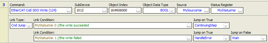
To check both the Done and Error bits, and take action based on which is set, use the Conditional Jump link type in a user program.
For example, the user program below uses the EtherCAT CoE SDO Write (124) command to write the value in variable MySourceVar to object 0x6060, subindex 0 in SubDevice 1012. The DWORD variable MyStatusVar is used as the Status Register. In the Conditional Jump Link Type, the first condition waits for bit 0 of MyStatusVar to be true, which indicates that the write completed successfully. The second condition waits for bit 1 of MyStatusVar, which indicates that the write failed. Each of the conditions jumps to a specific step, which should take the proper actions.
See Also
EtherCAT CoE SDO Read (123) | EtherCAT SDO | EtherCAT Overview
Copyright © 2026 Delta Computer Systems, Inc. dba Delta Motion