Download the Step Table to the RMC100 by clicking the download button on the Event Step Editor toolbar ( ).
).
To start the open loop step sequence in the positive direction on the axis:
The Tuning Wizard uses plots of the axis motion to compute the system model used for calculating the gains. This topic provides requirements, tips and procedures for creating plots that yield the best chances of creating an accurate system model.
Plot Requirements
Drive output must change during plot.
The plot must show the Drive output changing with corresponding movement on the axis.
Drive output should not cross the Null Drive value.
The Drive output should not cross the Null Drive value, which is typically near zero. That is, the move should only be in one direction. If the system is symmetrical, this condition does not need to be met.
Plot Tips
In addition to the requirements listed above, these tips will help improve the chances of creating an accurate system model:
The plot should show a combination of rapid transitions and steady or smooth sections of the Drive output.
The amplitude changes of the Drive output should be large enough so that they cause significant motion on the axis.
The plot time should generally be 1 or 2 seconds. Systems with very large masses (>10,000 lbs), or with very slow response times, may require a longer plot time.
The Extra Plot Data (selected in Plot Options) should be set to Extra Precision, which is the default setting.
Avoid non-linear regions of the valve, which may be near 0V or 10V on some valves.
Procedures for Obtaining Plots
To obtain plots for the Tuning Wizard, Delta recommends using Event Step sequences to generate a series of moves. Some sample step sequences are included at the end of this topic.
If you do not yet have any gains for the axes, you can make Open Loop moves. If you already have some gains that keep the axis stable, you can make Closed Loop moves.
Warning: In Open Loop, the safety features of the RMC100 are disabled. Take extra precautions to keep the axis from moving too fast or too far. Be prepared to stop the axis immediately with an emergency stop switch.
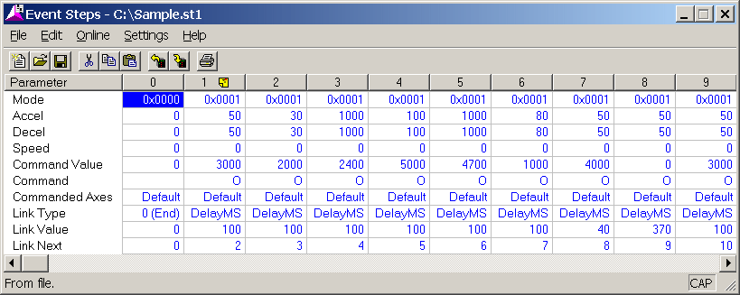
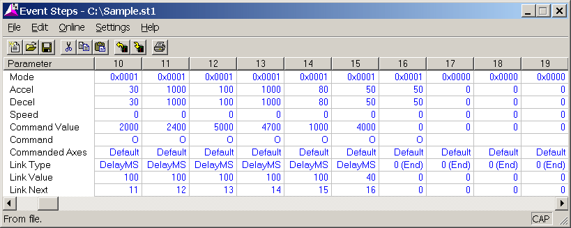
The sequence of steps starting at step 1 of the sample step sequence below generates an output with various ramps and small steps which should move the axis in the positive direction. The motion will be somewhat jerky due to the step changes in output voltage. The sequence can be changed to achieve slower voltage changes for systems with large masses.
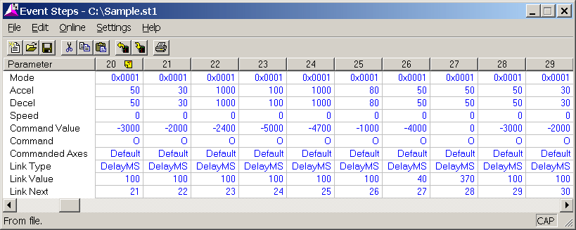
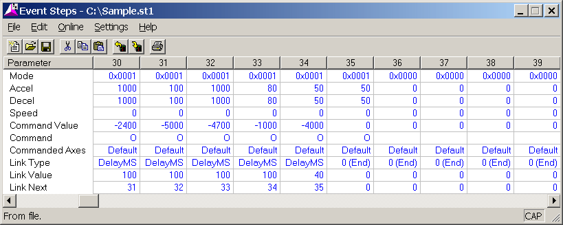
The sequence of steps starting at step 20 should move the axis in the negative direction.
Note: Some of the safety features of closed loop moves may stop the axis before it has moved far enough to obtain sufficient data for tuning. You may need to temporarily disable some of the Auto Stops or increase the Following Error window. Use caution when moving the axis with disabled the Auto Stops. Remember to set the Auto Stops to a safe setting after you have completed tuning the axis.
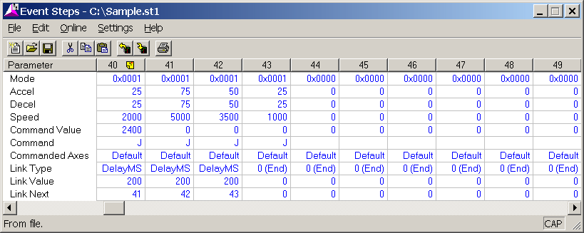
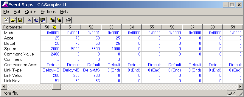
The step sequences starting at steps 40 and 50 are examples of moves that can be used to generate plots for the tuning wizard in the positive and negative directions respectively.
NOTE: You will need to edit the positions and speeds to make the sample step sequence work for your axis.
Steps to Create Open Loop Motion and Capture a Plot
Follow these steps to capture a plot containing sufficient data to build a model:
In RMCWin, on the Tools menu, click Event Steps Editor.
Enter an event step sequence in the Event Steps Editor. Use the sample sequences shown in this topic. You may need to modify them to suit your system.
Note: The sample step sequence shown in this topic, TuneWizDemo.st1, is located in the same folder as RMCWin, which is by default C:\Program Files\RMCWin\.
Download the Step Table to the RMC100 by clicking the download button on the Event Step Editor toolbar ( ).
).
To start the open loop step sequence in the positive direction on the axis:
In the Command area in RMCWin, type "1" in the Command Value of the axis, then issue an E command to that axis.
WARNING: This step will cause the axis to move. Be prepared to stop the axis with an emergency stop switch.
Open the plot of the motion by clicking the Plot Selected Axis button on the RMCWin toolbar ( ).
).
Once the plot is finished uploading, save the plot and give it a meaningful name so that you know which direction of motion it contains, for example "ExtendOL.plt"
To start the open loop step sequence in the other direction on the axis:
In the Command area in RMCWin, type "20" in the Command Value of the axis, then issue an E command to that axis.
Open the plot of the motion by clicking the Plot Selected Axis button on the RMCWin toolbar ( ).
).
Once the plot is finished uploading, save the plot and give it a meaningful name so that you know which direction of motion it contains, for example "RetractOL.plt"
On the Tools menu, click Tuning Wizard. Follow the steps of the wizard. If you have a standard single-rod cylinder, be sure to select "My System is Asymmetrical". When asked to build a model from a plot, use the plots you have saved.
Sample Step Sequences
Copyright (c) 1997-2015 by Delta Computer Systems, Inc.