When using a Modicon PLC with the Modbus Plus or Modbus/TCP network, the MSTR (for MaSTeR) ladder logic function block must be used. Before reading this topic for use with Modbus Plus, you should understand Reading and Writing Modbus Plus Registers and Using Modbus Plus Global Data. Before reading this topic for use with Modbus/TCP, you should understand Using the Modicon Quantum with the RMC Ethernet Module.
For complete documentation on this function block, refer to the Modicon Ladder Logic Block Library User Guide available from Schneider Electric. This topic uses information from the above text and will describe the aspects of this block that apply to using it with the RMC module.
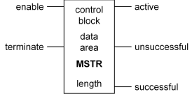
This function block takes the following form:

Inputs
There are two control inputs:
Enable: This input must be ON for the duration of an operation
Terminate: This input terminates the active operation when ON
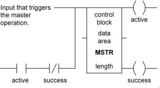
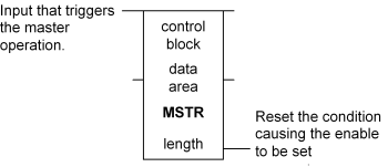
You must keep the enable input on for the duration of the operation. The following two ladders accomplish this in different ways:


In the second method, you must not reset the condition that triggers the MSTR block until the block completes.
Outputs
There are three possible outputs:
Active: This output will be ON while an operation is in progress
Unsuccessful: The operation failed. Refer to the Error Status register described below under Control Block for details on the failure.
Successful: The operation completed successfully
Control Block
A 4x (holding) register is given in this field (node). This register is the first of nine contiguous holding registers that comprise the control block:
|
Register |
Content |
|
1st |
Operation: There are nine operation types, but only these four are used during normal operation and documented here: 1: Write data (click here for details and example) 2: Read data (click here for details and example) 6: Read Global Data (Modbus Plus only) (click here for details and example) 9: Peer Cop Health (Modbus Plus only) (click here for details and example) |
|
2nd |
Error Status:This register is filled by the operation. See MSTR Block Error Codes for a complete list. |
|
3rd |
Length: Indicates the number of registers to transfer. |
|
4th |
Operation-dependent Value: Write: Indicates the register address in the slave to write to Read: Indicates the register address in the slave to read from Read Global Data: Gets filled by the PLC with the number of registers of global data available from the slave Peer Cop Health: Gives the number of registers to read from the Peer Cop Health map. |
|
5th-9th |
Routing 1-5: Read/Write Data: The uses of these fields depend on whether Modbus Plus or Modbus/TCP is being used. Modbus Plus: For local addresses, Routing 1 gives the node address, and Routing 2 gives the data path (1-8) to use in the node. Routing 3 through 5 are zeros. For more complicated routing methods, refer to the section on routing path structure in Modbus Plus Network Planning and Installation Guide. Modbus/TCP: Routing 1 is broken into two bytes: the MSB holds the Quantum backplane Slot ID of the NOE module, and the LSB holds the Map Index, which should be zero for the RMC. Routing 2 through 5 holds the four dot-separated values of the RMC IP address (e.g. 192.168.0.5). Global Data: Routing 1 gives the address of the node to read global data from. Routing 2 through 5 are zeros. Peer Cop Health: Unused. |
Data area
A 4x (holding) register is given in this field (node). This register is the first of a block of data that will either be written to the slave (in the case of a Write Data operation) or read into from the slave (in the case of Read Data and Read Global Data operations).
Length
This integer gives the number of registers available for reading and writing in the data area. Notice that this value serves as a maximum and does not indicate the actual number of registers written or read, which is given in the 3rd register in the Control Block.
Copyright (c) 1997-2015 by Delta Computer Systems, Inc.